Support structure and display device
A technology of supporting structure and flexible display, applied in identification devices, housings with display/control units, photovoltaic power generation, etc., can solve the problems of bending resistance, poor impact resistance, reduced reliability and stability, etc. Enhanced impact resistance, improved reliability and stability, improved flatness
- Summary
- Abstract
- Description
- Claims
- Application Information
AI Technical Summary
Problems solved by technology
Method used
Image

Examples
Embodiment 1
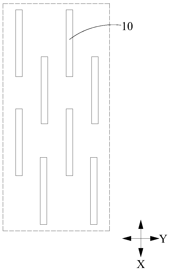
[0092] Such as image 3 As shown, the plurality of hollow holes in the first hollow pattern may include a first hollow group and a second hollow group arranged at intervals in the first direction X, and both the first hollow group and the second hollow group are included in the second direction Y The first hollow holes 11 and the first hollow holes 12 arranged at intervals; wherein, the first hollow holes 11 and the first hollow holes 12 are elongated, and the first hollow holes 11 extend in the first direction X, and the first hollow holes 11 extend in the first direction X. A hollow hole 12 extends in the second direction Y.
[0093] In this embodiment, setting the first hollow hole 11 can ensure the deformation amount of the first bendable area A of the support structure in the bending direction, and setting the first hollow hole 12 can appropriately relieve the first bendable area A of the support structure. The amount of deformation of the bending area A in the non-bendi...
Embodiment 2
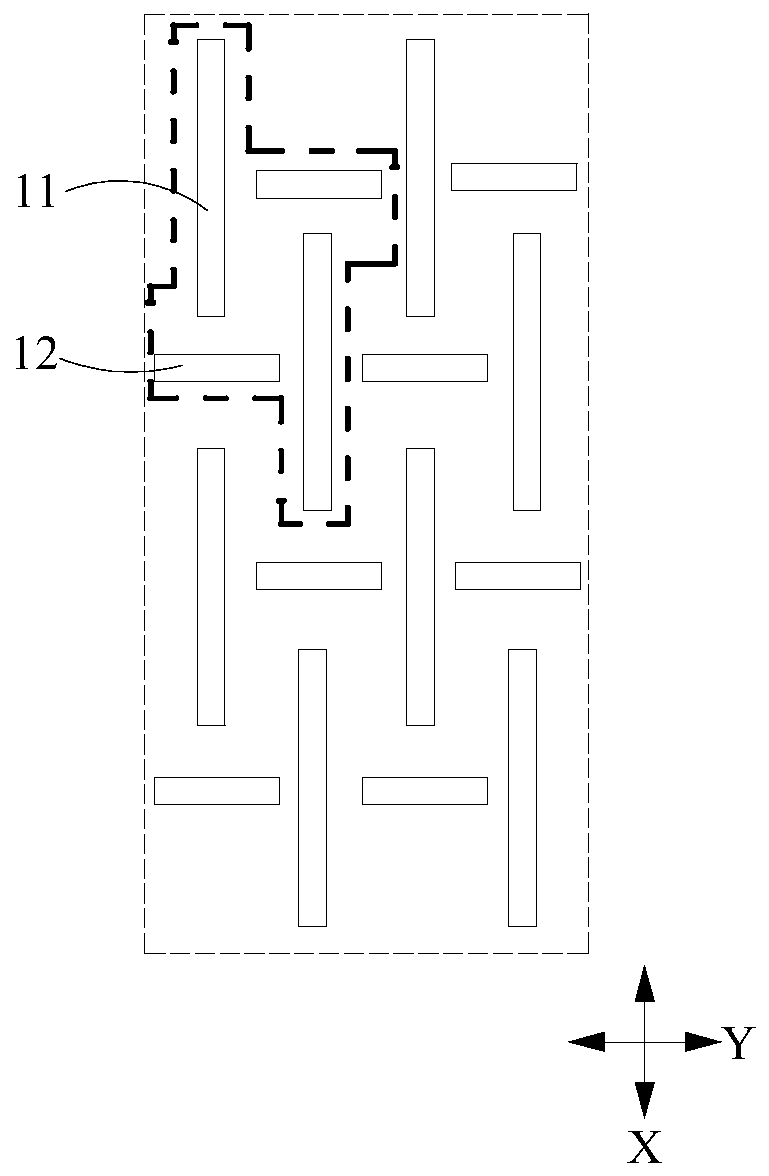
[0098] Such as Figure 4 As shown, the plurality of hollow holes in the first hollow pattern may include a first hollow group and a second hollow group. The first hollow group may include two first hollow holes 11 spaced apart in the first direction X and facing each other, while the second hollow group may include two first hollow holes 12 spaced apart and opposite in the second direction Y. Optionally, both the first hollow hole 11 and the first hollow hole 12 are elongated, the first hollow hole 11 extends in the first direction X, and the first hollow hole 12 extends in the second direction Y.
[0099] In this embodiment, setting the first hollow hole 11 can ensure the deformation amount of the first bendable area A of the support structure in the bending direction, and setting the first hollow hole 12 can appropriately relieve the first bendable area A of the support structure. The amount of deformation of the bending area A in the non-bending direction, so that when the...
Embodiment 3
[0102] Such as Figure 5 As shown, the plurality of hollow holes in the first hollow pattern include a third hollow group and a fourth hollow group. The third hollow group includes two third hollow holes 13 spaced apart in the third direction Q and facing each other, and the two third hollow holes 13 in the third hollow group are arranged symmetrically with respect to the center of the third hollow group; the fourth hollow The group includes two fourth hollow holes 14 that are spaced and opposite in the fourth direction P; and the two fourth hollow holes 14 in the fourth hollow group are arranged symmetrically with respect to the center of the fourth hollow group; wherein: the third hollow group The center of the center and the center of the fourth hollow group coincide with the center of the hollow group; the third hollow hole 13 and the fourth hollow hole 14 are elongated, the third hollow hole 13 extends in the third direction Q, and the third hollow hole 13 extends in the ...
PUM
 Abstract
Description
Claims
Application Information
 - Generate Ideas
- Intellectual Property
- Life Sciences
- Materials
- Tech Scout
- Unparalleled Data Quality
- Higher Quality Content
- 60% Fewer Hallucinations
Browse by: Latest US Patents, China's latest patents, Technical Efficacy Thesaurus, Application Domain, Technology Topic, Popular Technical Reports.
© 2025 PatSnap. All rights reserved.Legal|Privacy policy|Modern Slavery Act Transparency Statement|Sitemap|About US| Contact US: help@patsnap.com