Check patentability & draft patents in minutes with Patsnap Eureka AI!

Active phased array antenna

A phased array antenna and antenna unit technology, applied in the field of communication, can solve the problems of increasing the weight of the antenna platform, power consumption, fast beam scanning speed, and reducing the reliability of the platform, and achieve the goals of overcoming index deterioration, low cost, and weight reduction Effect

Pending Publication Date: 2020-01-14
CETC YANGZHOU BAOJUN ELECTRONICS
View PDF0 Cites 4 Cited by
  • Summary
  • Abstract
  • Description
  • Claims
  • Application Information

AI Technical Summary

Problems solved by technology

When scanning with a large angular span, the angular velocity of the turntable affects the beam pointing scanning speed of the antenna, and the beam switching time reaches more than a few hundred milliseconds, which is still slow for system applications; at the same time, because the servo turntable is used, the antenna platform is increased The weight, power consumption, complex operation, and reduced reliability of the platform have brought a series of disadvantages; when the combination of planar phased array is used for scanning, the scanning speed of the antenna beam is high, and the 360° scanning of the airspace azimuth plane The speed of the circle can reach within tens of microseconds, but the performance of the planar phased array antenna decreases rapidly with the increase of the beam scanning angle. Generally, when the beam scanning is ±60°, the antenna gain decreases by 3dB~5dB, and the beam width increases by 2~ 3 times, the side lobe level is increased by 5dB~10dB, accompanied by serious distortion of the lobe shape, these changes directly affect the performance of the antenna in some specific angle ranges when scanning the azimuth plane 360°
[0004] When the active phased antenna requires 360-degree scanning coverage of the azimuth plane, and at the same time it needs to maintain stable antenna beam performance and fast beam scanning speed, the above two methods cannot be achieved.

Method used


Image

  • Active phased array antenna
  • Active phased array antenna
  • Active phased array antenna

Examples


Embodiment

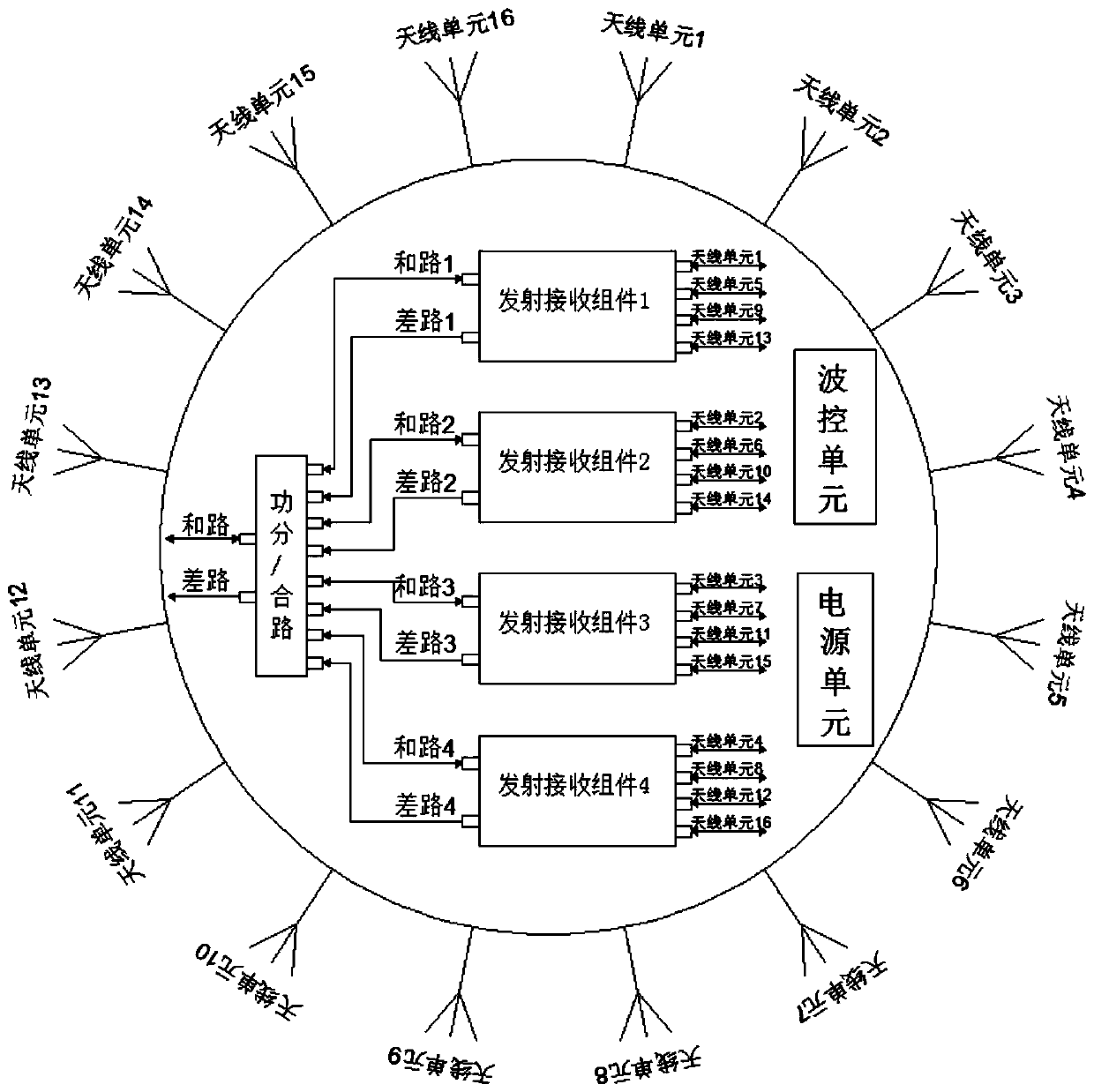
[0027] Example: such as Figure 1-3 As shown, an active phased array antenna includes an antenna array and an internal active network. The antenna array includes 16 antenna elements uniformly distributed on the circumference, and the antenna elements are uniformly arranged at intervals of 22.5°. The source network includes a power splitting / combining module, 4 transmitting and receiving components, a wave control unit and a power supply unit. The power dividing / combining module is connected to 4 transmitting and receiving components at the same time, and each transmitting and receiving component is connected to 4 The antenna units equidistant from each other are connected by radio frequency cables. The wave control unit is connected with the 4 transmitting and receiving components and controls the phase shift value and transmitting and receiving output power values ​​of the 4 transmitting and receiving components. The power supply part stabilizes the external input power, Afte...


PUM


Abstract

The invention discloses an active phased array antenna in the field of communication. The active phased array antenna comprises an antenna array plane and an internal active network, wherein the antenna array surface comprises a plurality of antenna units which are circumferentially and uniformly distributed, the internal active network comprises a power dividing / combining module, a plurality of transmitting and receiving assemblies, a wave control unit and a power supply unit; the power dividing / combining module is connected with the transmitting and receiving assemblies, the transmitting andreceiving assemblies are connected with the plurality of antenna units, and the wave control unit is connected with the transmitting and receiving assemblies. According to the active phased array antenna, the cost is effectively reduced, and meanwhile, 360-degree rapid electric scanning on the azimuth plane can be achieved; a servo turntable is omitted, so that the weight of the whole system is reduced, and the power consumption is reduced; the defects of index deterioration and the like caused by planar phased array combination during large-angle electric scanning are overcome, the performance is excellent, the cost is low, and the application range is wide.

Description

technical field [0001] The invention relates to the technical field of communication, in particular to an active phased array antenna. Background technique [0002] Active phased array antennas have been widely used in various occasions because of their advantages such as microsecond-level fast scanning of antenna beams, agility of antenna beam waveforms, spatial power combining capabilities, and easy installation of platform conformality. The planar active phased array antenna has become the main form of active phased array antenna due to its mature theory, relatively simple manufacturing process and reliable performance. When the active phased array antenna needs to scan the airspace with a full range of 360° beams, there are currently two main scanning modes: one is that the active phased array antenna is installed on a servo turntable that can rotate 360° in azimuth, Through the combination of electric scanning and machine scanning, fast electric scanning can be perform...

Claims


Application Information

Patent Timeline
Patent Type & Authority Applications(China)
IPC IPC(8): H01Q23/00H01Q21/28
CPCH01Q21/28H01Q23/00
Inventor 赵熠明符友丁钟鸣
Owner CETC YANGZHOU BAOJUN ELECTRONICS
Features
  • R&D
  • Intellectual Property
  • Life Sciences
  • Materials
  • Tech Scout
  • Unparalleled Data Quality
  • Higher Quality Content
  • 60% Fewer Hallucinations
Learn More