High voltage transmission line power taking method and device based on capacitive reactance matching shunt control

A high-voltage transmission line and high-voltage transmission technology, applied in the direction of circuit devices, electrical components, etc., can solve the problems of small, generally only about 1W, limited charging and discharging life of batteries, and decreased magnetic permeability of magnetic cores, etc., to achieve a wide range of power extraction , low cost and long service life

Active Publication Date: 2020-01-14
CHANGSHA UNIVERSITY OF SCIENCE AND TECHNOLOGY
View PDF3 Cites 6 Cited by
  • Summary
  • Abstract
  • Description
  • Claims
  • Application Information

AI Technical Summary

Problems solved by technology

The battery power supply can only supply power for low-power devices for a long time, and it is not suitable for the situation where the power supply power reaches tens of watts, and the battery charge and discharge life is limited, and the battery needs to be replaced regularly; solar power supply is greatly affected by the weather and environment, and the output The power fluctuation is large, so it is difficult to apply to the power supply requirements of large-scale online monitoring equipment; the conventional current transformer power supply is to put the open-gap current transformer on the transmission line, and the electromagnetic induction of the bus current acts on the circuit transformer to induce electric energy. In order to facilitate installation, this method uses an air-gapped current transformer, and the magnetic core permeability of the open-air-gapped current transformer will be extremely reduced, and the power induced by the secondary coil will be very small. Generally only about 1W

Method used


Image

  • High voltage transmission line power taking method and device based on capacitive reactance matching shunt control
  • High voltage transmission line power taking method and device based on capacitive reactance matching shunt control
  • High voltage transmission line power taking method and device based on capacitive reactance matching shunt control

Examples


Embodiment 1

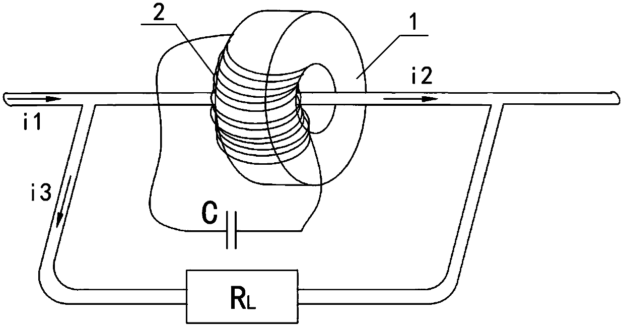
[0027] see figure 1 , the implementation steps of the high-voltage transmission line power extraction method based on capacitive reactance matching shunt control in this embodiment include:

[0028] 1) Put the air-gapped magnetic core 1 on the high-voltage power transmission cable so that the high-voltage power transmission cable constitutes the primary winding of the magnetic core 1, and the secondary winding 2 is wound on the magnetic core 1, and the output end of the secondary winding 2 is connected in series There is a matching capacitor C, so that the magnetic core 1, the secondary winding 2, the matching capacitor C and the high-voltage transmission cable together form a damping branch;

[0029] 2) On both sides of the magnetic core 1 on the high-voltage transmission cable, a shunt wire is connected with a clamp, and the energy harvesting branch is formed by the two shunt wires to output the electric energy obtained from the high-voltage transmission cable.

[0030] The...

Embodiment 2

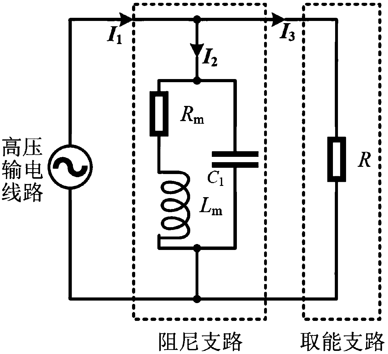
[0052] This embodiment is basically the same as Embodiment 1, and the difference is that in this embodiment, the matching capacitor C adopts a fixed capacitance value so that the matching capacitor C and the equivalent excitation inductance of the magnetic core (1) of the damping branch are excited in parallel, so that Achieve continuous maximum diversion. In this embodiment, the value of the matching capacitor C of the high-voltage transmission line power taking device based on capacitive reactance matching shunt control is shown in formula (1), so that the matching capacitor C is connected in parallel with the equivalent excitation inductance of the magnetic core 1 of the damping branch. excitation;

[0053]

[0054] In the formula (1), C is the capacitance value of the matching capacitor C, and C 1 is the equivalent capacitance of the primary side, N 2 is the number of turns of secondary winding 2, L m The equivalent magnetizing inductance is induced for the magnetic ...


PUM


Abstract

The invention discloses a high voltage transmission line power taking method and device based on capacitive reactance matching shunt control. An air gap magnetic core is inserted into a power transmission cable, and a matching capacitor C with certain capacitance value is connected with the secondary winding of the magnetic core to form a damping branch. On the power transmission cable on both ends of the magnetic core, a load is connected with the high-voltage power transmission cable through a shunt line through a clamp to form an energy taking branch. By setting the capacitance value to enable the equivalent excitation inductor of the magnetic core to carry out parallel resonance, the equivalent impedance of the damping branch is significantly increased, and the bus current is divided into the energy taking branch. The current of the energy taking branch is increased, and the current of the damping branch is decreased to provide high-power electrical energy through the energy takingbranch. According to the invention, the method and device are not affected by weather and climate; the overall power taking volume is small, so that the installation is easy; the device can take a large amount of power from a transmission bus, and can continuously and stably provide sufficient power for the online monitoring equipment of a transmission line; and the reliability of the online monitoring equipment of the transmission line is improved.

Description

technical field [0001] The invention relates to a power supply technology for real-time on-line monitoring equipment of a high-voltage transmission line, in particular to a method and device for taking power from a high-voltage transmission line based on capacitive reactance matching shunt control. Background technique [0002] In the power grid, extensive real-time monitoring of the insulator leakage current, ice thickness, temperature and load of the high-voltage overhead transmission line can detect and eliminate faults in the transmission line in time, which is of great significance to the safety and stability of the power system. However, the power supply for real-time monitoring equipment of high-voltage transmission lines is not easy to obtain, and this has always been an important problem that limits the wide application of online real-time monitoring of transmission lines. At present, conventional energy supply methods include battery power supply, solar power suppl...

Claims


Application Information

Patent Timeline
Patent Type & Authority Applications(China)
IPC IPC(8): H02J5/00H02J50/10
CPCH02J50/10
Inventor 刘铮樊绍胜杨军卢新星胡劼睿张鹏
Owner CHANGSHA UNIVERSITY OF SCIENCE AND TECHNOLOGY
Why Eureka
Try Eureka