

Machine tool for sliding shoe closing
A sliding shoe and machine tool technology, which is applied in the field of plunger assembly assembly, can solve the problems of poor screwing accuracy and stability of the sliding shoe closure, low yield rate, etc., and achieve the effect of smooth movement, good stability, and good spinning stability
- Summary
- Abstract
- Description
- Claims
- Application Information
AI Technical Summary
Problems solved by technology
Method used
Image

Examples
Embodiment 1
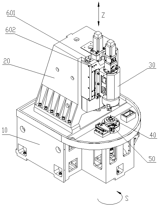
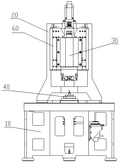
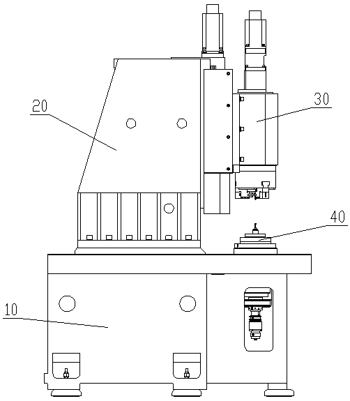
[0036] see figure 1 , figure 2 and Figure 4 , a machine tool for sliding shoe closing, including a bed 10, a column 20 and a workpiece spindle 40 for clamping the shoe are fixedly connected to the bed 10, and a sliding mechanism is fixedly connected to the column 20 60, the sliding mechanism 60 is connected with a spinning mechanism 30 for spinning shoes, the spinning mechanism 30 is located directly above the workpiece spindle 40, and the spinning mechanism 30 includes a chuck 305, a roller assembly 307 and a The top assembly 306 that tightens the plunger ball head, the roller assembly 307 is installed on the base jaw of the chuck 305, the top assembly 306 is installed at the center of the chuck 305, and the bed 10 is equipped with a manipulator 50 , the manipulator 50 is located on one side of the workpiece spindle 40 , and the rotation axis of the spinning mechanism 30 is coaxial with the rotation axis of the workpiece spindle 40 .
[0037] This embodiment is the most ...
Embodiment 2
[0039] see figure 1 , figure 2 , Figure 4 and Figure 5 , a machine tool for sliding shoe closing, including a bed 10, a column 20 and a workpiece spindle 40 for clamping the shoe are fixedly connected to the bed 10, and a sliding mechanism is fixedly connected to the column 20 60, the sliding mechanism 60 is connected with a spinning mechanism 30 for spinning shoes, the spinning mechanism 30 is located directly above the workpiece spindle 40, and the spinning mechanism 30 includes a chuck 305, a roller assembly 307 and a The top assembly 306 that tightens the plunger ball head, the roller assembly 307 is installed on the base jaw of the chuck 305, the top assembly 306 is installed at the center of the chuck 305, and the bed 10 is equipped with a manipulator 50 , the manipulator 50 is located on one side of the workpiece spindle 40 , and the rotation axis of the spinning mechanism 30 is coaxial with the rotation axis of the workpiece spindle 40 .
[0040] The workpiece s...
Embodiment 3
[0043] see figure 1 , figure 2 , Figure 4 and Figure 5 , a machine tool for sliding shoe closing, including a bed 10, a column 20 and a workpiece spindle 40 for clamping the shoe are fixedly connected to the bed 10, and a sliding mechanism is fixedly connected to the column 20 60, the sliding mechanism 60 is connected with a spinning mechanism 30 for spinning shoes, the spinning mechanism 30 is located directly above the workpiece spindle 40, and the spinning mechanism 30 includes a chuck 305, a roller assembly 307 and a The top assembly 306 that tightens the plunger ball head, the roller assembly 307 is installed on the base jaw of the chuck 305, the top assembly 306 is installed at the center of the chuck 305, and the bed 10 is equipped with a manipulator 50 , the manipulator 50 is located on one side of the workpiece spindle 40 , and the rotation axis of the spinning mechanism 30 is coaxial with the rotation axis of the workpiece spindle 40 .
[0044] The workpiece s...
PUM
 Abstract
Description
Claims
Application Information