Steel bar net cage net combining method

A steel mesh and networking technology, applied to the online network, other household appliances, household appliances, etc., can solve the problems of labor-intensive, not well adapted to the production of autoclaved aerated concrete, and low networking efficiency, so as to improve efficiency , to ensure accuracy, and to speed up the effect of networking

Active Publication Date: 2020-01-17
ANHUI KEDA IND CO LTD
View PDF6 Cites 2 Cited by
  • Summary
  • Abstract
  • Description
  • Claims
  • Application Information

AI Technical Summary

Problems solved by technology

[0006] Aiming at the problems in the prior art that the networking of reinforced mesh cages is labor-intensive and the networking efficiency is low, and cannot be well adapted to the production of autoclaved aerated concrete, the present invention provides a method for networking of reinforced mesh cages; The reinforced mesh cage is positioned according to the production requirements, which saves the process of manual hanging and positioning, and the hanging mesh is positioned accurately and has a high degree of automation, which improves the networking efficiency of the reinforced mesh cage.

Method used


Image

  • Steel bar net cage net combining method
  • Steel bar net cage net combining method
  • Steel bar net cage net combining method

Examples


Embodiment 1

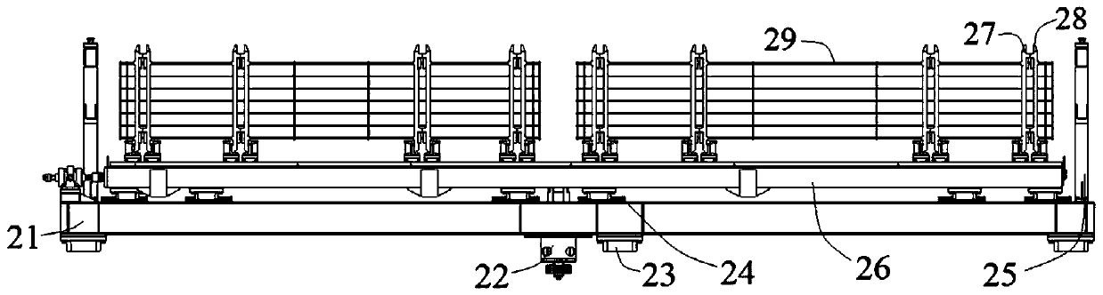
[0049] combine image 3 , a reinforced mesh cage networking trolley in this embodiment includes a first trolley frame 21 , a first moving frame 26 , a first moving assembly 27 , a second moving assembly 28 and a second moving frame 210 . The first moving assembly 27 can be provided with different numbers along the length direction of the first moving frame 26 according to the steel mesh cage 29 of different specifications. Specifically, in this embodiment, 8 first moving assemblies are arranged along the length direction of the first moving frame 26 27. The second moving assembly 28 can be provided with different numbers along the length direction of the second moving frame 210 according to the reinforced mesh cage 29 of different specifications. Components 28, the first moving component 27 and the second moving component 28 are arranged in pairs, and cooperate with each other to position and fix the steel mesh cage 29.

[0050] combine Figure 8 , the second moving frame 2...

Embodiment 2

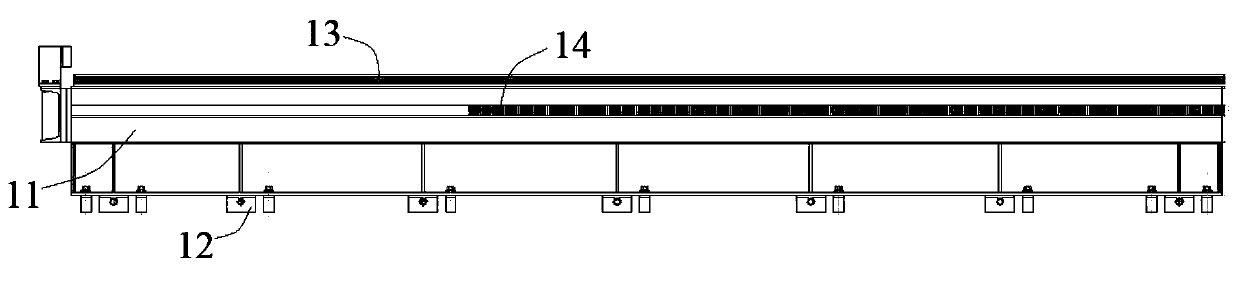
[0054] combine figure 2 , this embodiment relates to a kind of network equipment using a network trolley for reinforced mesh cage networking, including a base 1 and a networking trolley as described in Embodiment 1, the base 1 includes a base frame 11, a shim 12, a base guide rail 13 and Transmission rack 14. The base guide rail 13 and the transmission rack 14 are arranged on the base frame 11 along the length direction, and the shims 12 are arranged at intervals along the length direction of the base frame 11 for adjusting the height of the base frame 11 . The lower end of the networking trolley is provided with a transmission assembly 22 and a first slider 23, the transmission assembly 22 includes a gear 221 and a transmission base 222, the bottom of the networking trolley is provided with a transmission base 222, and the transmission base 222 is connected to the gear 221, and the gear 221 is connected to the base 1 gear rack 14 engagement. The gear 221 of the transmissio...

Embodiment 3

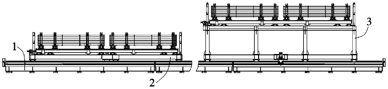
[0056] combine figure 1 and Figure 5 , a reinforced mesh cage networking equipment in this embodiment is basically the same as in Embodiment 2, except that the networking equipment includes two networking trolleys, that is, the first trolley 2 and the second trolley 3, wherein the first trolley The second trolley frame 31 of the second trolley 3 is higher than the first trolley frame 21 of the first trolley 2, the two trolleys are arranged in layers, and the base 1 is respectively provided with a base for the first trolley 2 and the second trolley 3 The guide rail 13 and the transmission rack 14 enable the two trolleys to move back and forth on the base 1 at the same time, and form a network separately without interfering with each other, thereby improving the efficiency of the network.


PUM


Abstract

The invention discloses a steel bar net cage net combining method and relates to the technical field of steel bar net cage automatic net combining. According to the steel bar net cage net combining method, a base is provided with two net combining trolleys, each net combining trolley is provided with first moving racks, first moving components, second moving components and second moving racks, thefirst moving racks drive the first moving components to move, the second moving racks drive the second moving components to move, positioning holes combined by semi-guiding bodies on the two moving components perform positioning fixing on connecting pieces, meanwhile, guiding holes perform guiding on insert-in of steel chisels, accurate placement of steel bar net cages in the net combining process is guaranteed, the accuracy of the net combining process is guaranteed at the same time, and meanwhile, the labor is saved.

Description

technical field [0001] The invention relates to the technical field of automatic networking of reinforced mesh cages, and more specifically, relates to a method for networking of reinforced mesh cages. Background technique [0002] Autoclaved aerated concrete blocks are porous concrete products made of sand or fly ash as the main raw material, cement lime, gypsum and other substances are added, and the process of batching, mixing, pouring and other processes is manufactured. Compared with traditional ordinary clay bricks, autoclaved aerated concrete blocks can improve the thermal insulation performance of building walls and improve the energy-saving effect of buildings. In the production process of autoclaved aerated concrete block slabs, it is necessary to add steel mesh cages to the slabs to enhance its structural stability; after welding a single piece of steel mesh to form a steel mesh cage, the steel mesh cage needs to be hung on Networking is carried out on steel braz...

Claims


Application Information

Patent Timeline
Patent Type & Authority Applications(China)
IPC IPC(8): B21F27/20B21F23/00
CPCB21F23/005B21F27/20
Inventor 吴亚军齐国良申干强王文昌徐顺武
Owner ANHUI KEDA IND CO LTD
Why Eureka
Try Eureka