Apparatus and method of installing pre-molded seal caps

A sealed lid, pre-formed technology for packaging sealing/fastening, packaging item type, packaging, etc., which can solve the problems of manufacturing cycle time and cost impact, cumbersome procedures and steps, time-consuming, etc.

Pending Publication Date: 2020-01-17
THE BOEING CO
View PDF0 Cites 4 Cited by
  • Summary
  • Abstract
  • Description
  • Claims
  • Application Information

AI Technical Summary

Problems solved by technology

As these procedures and steps are cumbersome and time consuming, manual instal...

Method used


Image

  • Apparatus and method of installing pre-molded seal caps
  • Apparatus and method of installing pre-molded seal caps
  • Apparatus and method of installing pre-molded seal caps

Examples


example 1

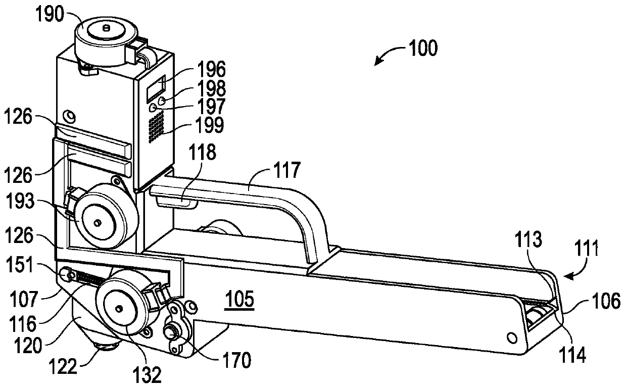
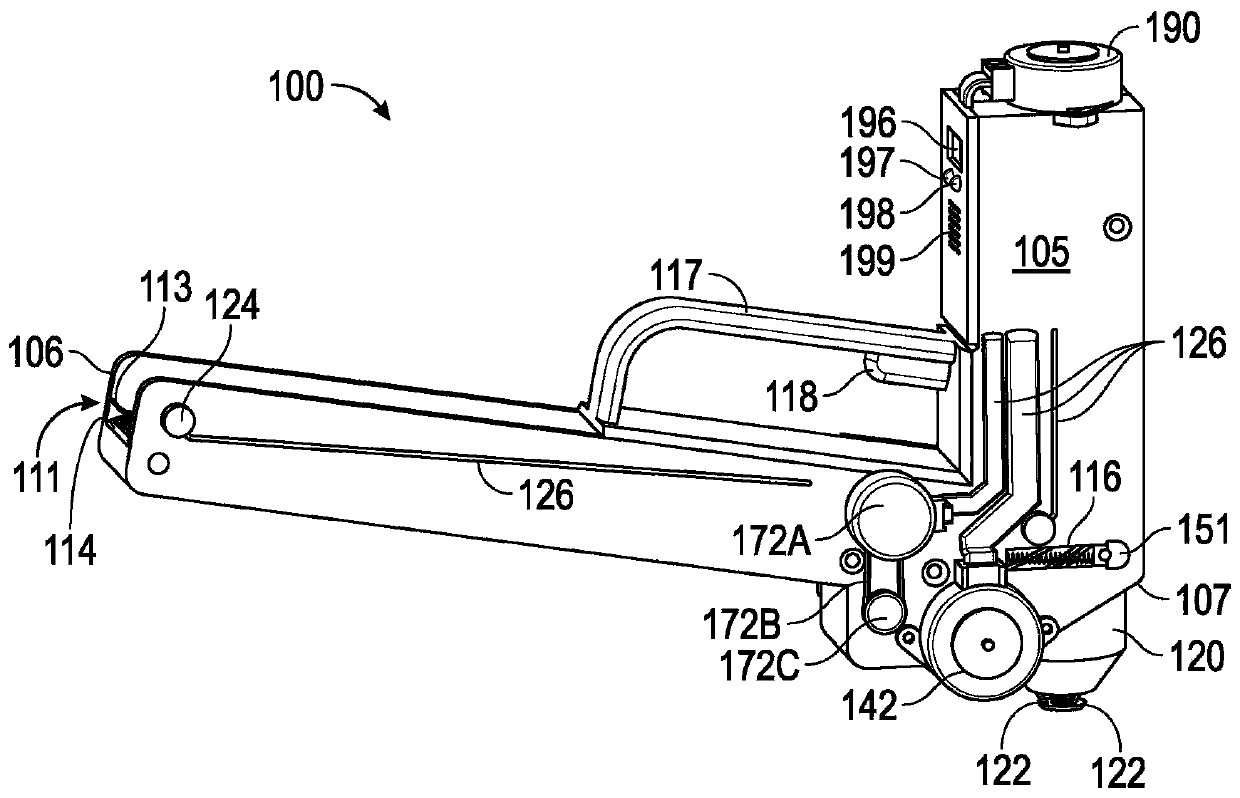
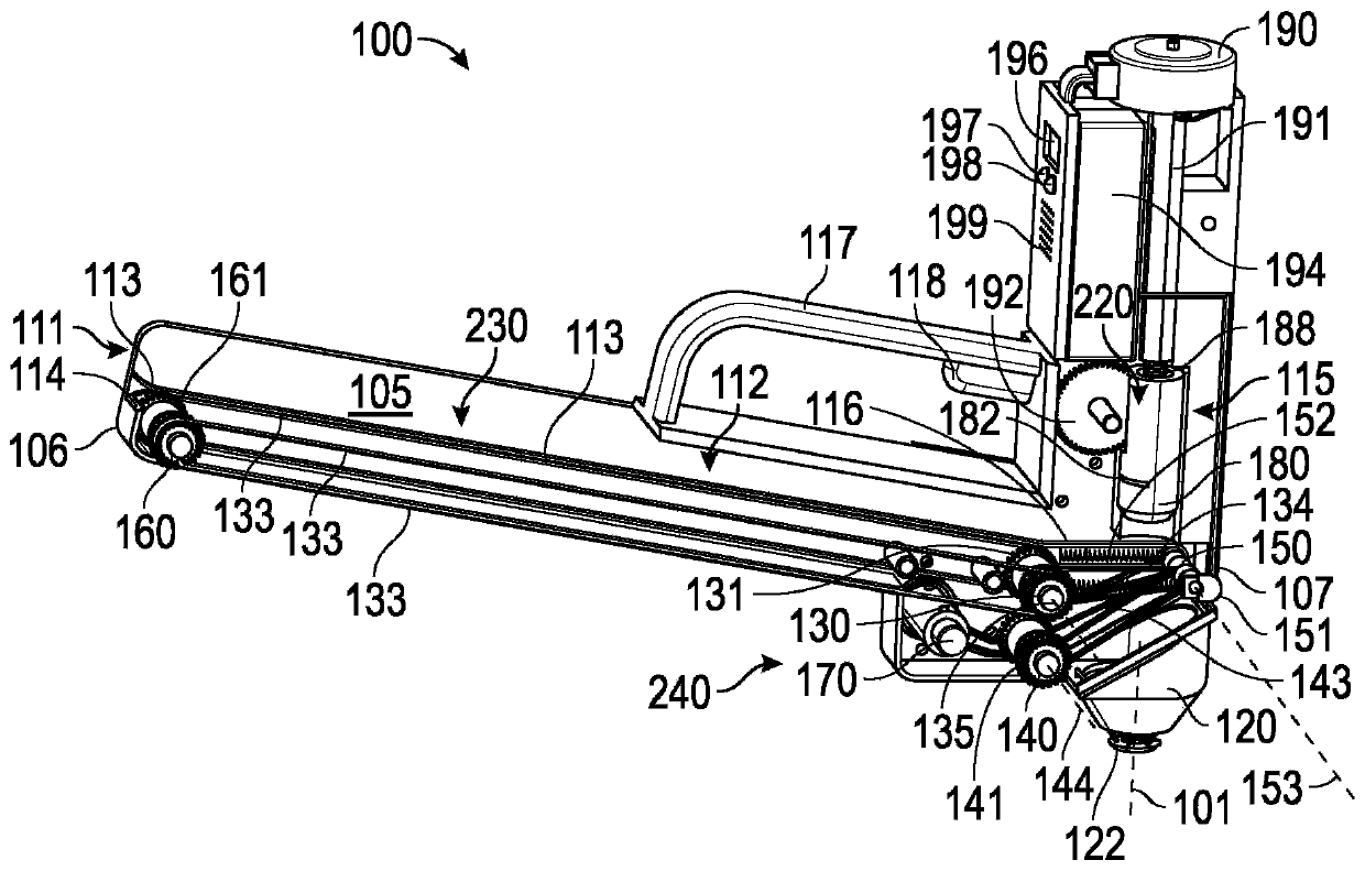
[0066] The device 100 is provided for mounting a preformed sealing cover 210 arranged on a carrier strip 200 on a fastener 301 extending from a surface 300 . The apparatus 100 is configured to individually remove the preformed sealing caps 210 from the carrier strip 200 one at a time and install the preformed sealing caps 210 removed from the carrier strip 200 individually onto the fasteners 301 extending from the surface 300 . Feed system 230 transports carrier tape 200 within apparatus 100 and cooperates with plunger mechanism 220 to sequentially remove preformed sealing caps 210 from carrier tape 200 . The plunger mechanism 220 installs the removed preformed sealing cap 210 onto the fastener 301 . Apparatus 100 is capable of automatically sequentially removing preformed sealing caps 210 from carrier tape 220 and installing the removed preformed sealing caps 210 onto fasteners 301 extending from surface 300 . The take-up mechanism 240 prevents the carrier tape 200 from beco...

example 2

[0068] general reference Figure 43A , 43B , 43C and 43D, and with particular reference to e.g. Figure 23-26 , the apparatus 100 further includes a control system 123 configured to activate the plunger mechanism 220 only when the plunger mechanism 220 has a predetermined angular orientation with respect to each of the selected plurality of fasteners in the fastener 301. After mechanism 220 individually removes preformed seal caps 210 from carrier tape 200 , plunger mechanism 220 is enabled to individually install preformed seal caps 210 onto selected ones of fasteners 301 . The foregoing subject matter of this paragraph characterizes Example 2 of the present disclosure, wherein Example 2 also includes subject matter according to Example 1 above.

[0069] Plunger mechanism 220 removes a single one of preformed sealing caps 210 from carrier tape 200 and installs preformed sealing caps 210 onto fasteners 301 extending from surface 300 . However, unless the plunger mechanism 2...

example 3

[0071] general reference Figure 43A , 43B , 43C and 43D, and in particular with reference to e.g. image 3 , 4 . The communicating outlet opening 121 . Feed system 230 is located within housing 105 and plunger mechanism 220 is located within chamber 115 . Feed system 230 is configured to transport carrier tape 200 to chamber 115 . The plunger mechanism 220 is configured to transport the preformed sealing cap 210 removed from the carrier tape 200 out of the chamber 115 of the housing 105 through the outlet opening 121 . The foregoing subject matter of this paragraph characterizes Example 3 of the present disclosure, wherein Example 3 also includes subject matter according to Example 2 above.

[0072] Entry opening 111 allows insertion of carrier tape 200 into housing 105 . The plunger mechanism 220 is located within the chamber 115 and is configured to move within the chamber 115 . Exit opening 121 allows plunger mechanism 220 to be moved out of housing 105 to install ...


PUM


Abstract

An apparatus (100) and method for mounting preformed seal covers (210) to a fastener (301) extending from a surface (300) is disclosed. The apparatus (100) includes a plunger mechanism (220) configured to individually mount the preformed seal cover (210) to a selected one of a plurality of fasteners (301). The apparatus (100) also includes a feed system (230) configured to sequentially convey thepreformed sealing covers (210) disposed on the carrier tape (200) to the plunger mechanism (220). The apparatus (100) additionally includes a collection mechanism (240) configured to collect the carrier tape (200) as the preformed sealing cover (210) are sequentially removed from the carrier tape (200). The plunger mechanism (220) is further configured to cooperate with the feed system (230) to sequentially remove the preformed seal covers (210) from the carrier tape (200).

Description

technical field [0001] The present disclosure relates to apparatus and methods for installing a sealing cap onto a fastener extending from a surface. Background technique [0002] The assembly of structures such as aircraft typically requires many fasteners. Traditionally, sealants are manually applied to exposed fasteners to protect them from corrosion, provide a fuel barrier, and / or provide protection from electromagnetic effects. Alternatively, a pre-formed sealing cap containing a sealant may be utilized. Before manually installing the pre-formed closures onto the fastener, an operator must manually remove the closures from their respective packaging. During installation, the operator must continuously rotate the pre-formed seal caps while pushing them over the fastener until proper uniform sealant extrusion occurs. The operator must also install the preformed closure in a direction perpendicular to the surface carrying the fastener to ensure that the preformed closur...

Claims


Application Information

Patent Timeline
IPC IPC(8): B23P19/00B23P19/04B23P21/00
CPCB65B1/02B65B29/02B65B51/10B23P19/00B23P19/001B23P19/04B23P21/00B25B23/045B25B27/0028B64D45/02F16B33/004F16B37/14B64D37/32B65G23/04B65G23/22B65G23/24B65G47/08F16B11/002F16B37/145
Inventor 约翰·M·布哈格史蒂芬·J·钱特
Owner THE BOEING CO
Why Eureka
Try Eureka