
Building floor elevation control and adjustment tool

A technology for controlling and adjusting floors and floors, which is applied in infrastructure engineering, architecture, and building construction. It can solve problems such as inability to install machinery, large deviations in surface elevation or flatness, waste of materials and labor, and reduce production costs. The effect of long service life and simple structure

Pending Publication Date: 2020-01-17
江苏通平建设工程有限公司
View PDF0 Cites 2 Cited by
  • Summary
  • Abstract
  • Description
  • Claims
  • Application Information

AI Technical Summary

Problems solved by technology

[0002] Due to the continuous increase of large-area (volume) buildings, the large-area basement floor, roof floor concrete, and the one-time formed emery floor on the floor concrete, the design elevation control point and the surface flatness, To achieve quality acceptance within the allowable deviation range of general items, the traditional construction technology has been difficult to meet the requirements of today's quality standard control
On the surface of a large basement or concrete surface of a cast-in-place floor, deviations of 30-50 mm in design elevation and flatness sometimes occur. In order to meet the requirements of construction acceptance specifications, only fine stone concrete or cement mortar is used to level the surface, so that Waste materials and labor, while increasing construction costs, but also increase the weight of the building
[0003] If there is a one-time-molded emery floor on the large-area floor of an industrial plant, the surface elevation or flatness deviation is large, which will lead to problems such as water accumulation on the floor surface and failure of machinery to be installed.

Method used


Image

  • Building floor elevation control and adjustment tool
  • Building floor elevation control and adjustment tool
  • Building floor elevation control and adjustment tool

Examples


Embodiment Construction

[0020] The following will clearly and completely describe the technical solutions in the embodiments of the present invention with reference to the accompanying drawings in the embodiments of the present invention. Obviously, the described embodiments are only some, not all, embodiments of the present invention. Based on the embodiments of the present invention, all other embodiments obtained by persons of ordinary skill in the art without making creative efforts belong to the protection scope of the present invention.

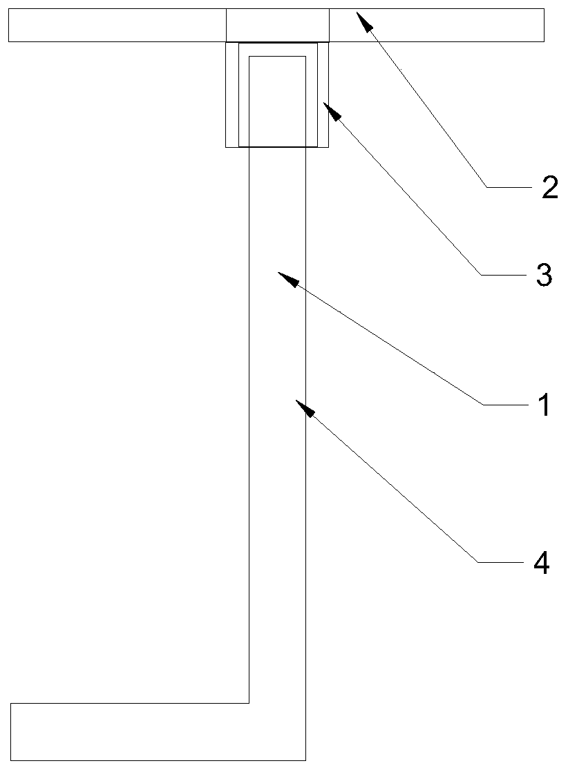
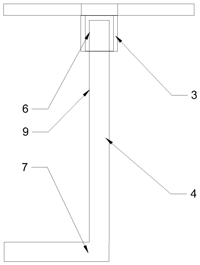
[0021] Such as figure 1 As shown, a floor elevation control and adjustment tool is used for pouring building floor concrete and a one-time formed emery floor on the floor concrete. The main body includes an adjustment roof device body 1, an adjustment iron plate 2, and an adjustment iron plate sleeve Cylinder 3, adjusting J-shaped support rod 4, adjusting the top plate device body 1 is provided with an adjusting iron plate 2, the middle and bottom of the adjus...


PUM

PropertyMeasurementUnit
Diameteraaaaaaaaaa

Abstract

The invention discloses a building floor elevation control and adjustment tool. A main body comprises an adjustment top plate device body, an adjustment iron plate sleeve and an adjustment J-shaped supporting rod, wherein the adjustment iron plate is arranged at the top of the adjustment top plate device body; the adjustment iron plate sleeve is arranged at the bottom end of the middle of the adjustment iron plate; and the lower part of the adjustment iron plate sleeve is connected with the adjustment J-shaped supporting rod. The building floor elevation control and adjustment tool is used forpouring building floor concrete and a carborundum building floor formed on the floor concrete at a time. The building floor elevation control and adjustment tool can be adjusted to the designed height for use according to the actual use condition and is suitable for serving as an elevation and supporting top beam in the building industry, height fine adjustment can be conducted by rotating the adjustment J-shaped supporting rod when deviation occurs, and the control and adjustment tool is invested at a time, convenient to mount and dismount and capable of being repeatedly used in a turnover mode.

Description

technical field [0001] The invention relates to the technical field of building construction equipment, in particular to a floor elevation control and adjustment tool. Background technique [0002] Due to the continuous increase of large-area (volume) buildings, the large-area basement floor, roof floor concrete, and the one-time formed emery floor on the floor concrete, the design elevation control point and the surface flatness, To achieve quality acceptance within the allowable deviation range of general items, the traditional construction technology has been difficult to meet the requirements of today's quality standard control. On the surface of a large basement or concrete surface of a cast-in-place floor, deviations of 30-50 mm in design elevation and flatness sometimes occur. In order to meet the requirements of construction acceptance specifications, only fine stone concrete or cement mortar is used to level the surface, so that Waste of materials and labor, while ...

Claims


Application Information

Patent Timeline
IPC IPC(8): E04G21/10E02D15/02E04F21/24
CPCE02D15/02E04F21/24E04G21/10
Inventor 曹华孙坚吴志锋倪树春
Owner 江苏通平建设工程有限公司
Learn More