
P-shaped pipe, P-shaped pipe forming process and P-shaped pipe forming equipment

A pipe forming and equipment technology, applied in the direction of pipes/pipe joints/pipe fittings, mechanical equipment, lighting and heating equipment, etc., can solve the problems of low production efficiency, high production cost, complicated process, etc., and achieve fast forming, operation and maintenance Convenience, the effect of reducing the production process steps

Inactive Publication Date: 2020-01-17
SUZHOU SAMSUNG ELECTRONICS CO LTD +1
View PDF8 Cites 1 Cited by
  • Summary
  • Abstract
  • Description
  • Claims
  • Application Information

AI Technical Summary

Problems solved by technology

[0006] The purpose of the present invention is to provide a P-shaped pipe, a P-shaped pipe forming process and a P-shaped pipe forming equipment, so as to solve the problems of the P-shaped pipe in the prior art, such as the complicated technological process, low production efficiency, and high production cost.

Method used


Image

  • P-shaped pipe, P-shaped pipe forming process and P-shaped pipe forming equipment
  • P-shaped pipe, P-shaped pipe forming process and P-shaped pipe forming equipment
  • P-shaped pipe, P-shaped pipe forming process and P-shaped pipe forming equipment

Examples


Embodiment Construction

[0031] The technical solutions of the present invention will be clearly and completely described below in conjunction with the accompanying drawings. Obviously, the described embodiments are part of the embodiments of the present invention, rather than all of them. Based on the embodiments of the present invention, all other embodiments obtained by those of ordinary skill in the art without creative work shall fall within the protection scope of the present invention.

[0032] In the description of the present invention, it should be noted that the terms "center", "upper", "lower", "left", "right", "vertical", "horizontal", "inner", "outer", etc. The indicated orientation or positional relationship is based on the orientation or positional relationship shown in the drawings, which is only for the convenience of describing the present invention and simplifying the description, rather than indicating or implying that the pointed device or element must have a specific orientation or ...


PUM

PropertyMeasurementUnit
widthaaaaaaaaaa

Abstract

The invention provides a P-shaped pipe, a P-shaped pipe forming process and P-shaped pipe forming equipment and relates to the technical field of refrigerating equipment. The P-shaped pipe comprises awide cavity part and a narrow cavity part. The wide cavity part and the narrow cavity part are distributed along the width direction of the P-shaped pipe and are integrally formed, and a piece is arranged on the end surface of the side, far away from the narrow cavity part, of the wide cavity part and stretches along the length of the P-shaped pipe. The P-shaped pipe is manufactured at one time by means of the P-shaped pipe forming process adopting a roll forming technology, and the piece is located on the side wall, far away from the narrow end, of the P-shaped pipe. The P-shaped forming equipment comprises a plurality of groups of forming rollers. Each group of forming rollers comprises an upper guide roller and a lower guide roller arranged oppositely up and down. The P-shaped pipe issimple in structure and free of welding, so that the manufacturing process is cut down. The P-shaped pipe forming process can form the P-shaped pipe directly at one time, so that the shape structure and the curvature of the P-shaped pipe are ensured, the assembling property of the P-shaped pipe is improved, and the production efficiency is improved. The P-shaped pipe forming equipment is low in manufacturing cost, rapid to form and convenient to operate and maintain.

Description

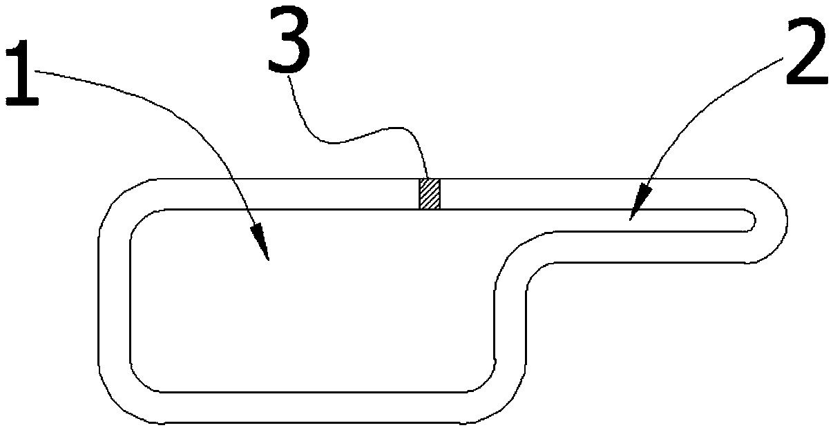
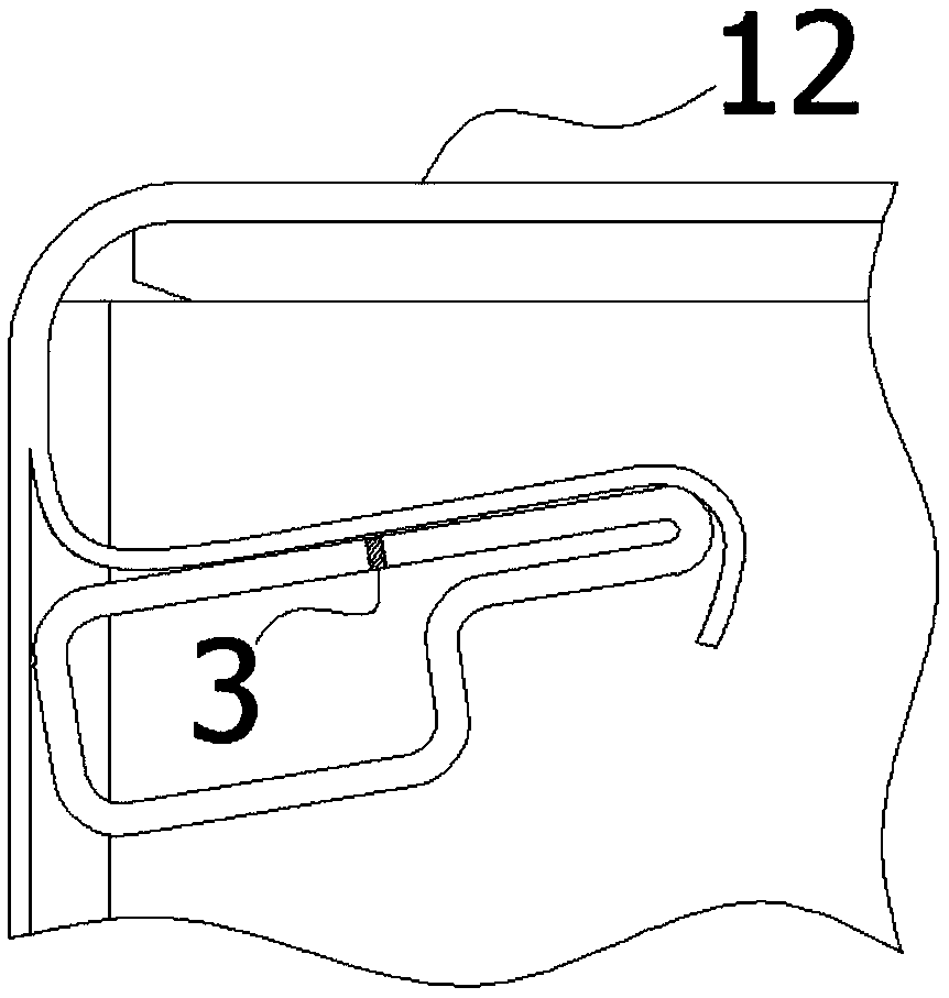
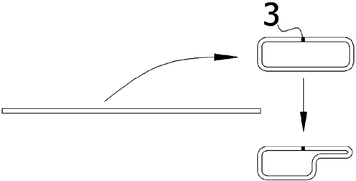
Technical field [0001] The invention relates to the technical field of refrigeration equipment, in particular to a P-shaped tube, a P-shaped tube forming process and a P-shaped tube forming device. Background technique [0002] High-strength P-shaped tubes are commonly used as structural reinforcements on refrigerators. figure 1 It is a sectional view of the P-shaped tube in the prior art; figure 2 It is a schematic diagram of the installation of the P-shaped tube in the refrigerator in the prior art; image 3 It is the production flow chart of the P-shaped tube in the prior art. In the prior art, the P-shaped tube for this purpose has a cross-section like figure 1 As shown, its use place is like figure 2 As shown, the production process is as image 3 Shown. [0003] Such as figure 1 , 3 As shown, the seam 3 (before welding) of the P-shaped tube is arranged on the upper surface with the largest plane area, and the seam 3 thus arranged is convenient for stamping and welding. And...

Claims


Application Information

Patent Timeline
Patent Type & Authority Applications(China)
IPC IPC(8): F16L9/02F16L9/04F25D23/00B21C37/15B21D5/12
CPCB21C37/15B21D5/12F16L9/02F16L9/04F25D23/00
Inventor 张科
Owner SUZHOU SAMSUNG ELECTRONICS CO LTD
Learn More