
Device and method for testing sealing performance of natural gas hydraulic drive pipeline of diesel engine

A test method and drive tube technology, applied in fluid tightness test, machine/structural component test, measuring device, etc., can solve problems such as narrow bench space, long time occupied by bench, inconvenient operation, etc., to avoid Safety hazards, shortened occupancy cycle, effects of quick connection and disassembly

Inactive Publication Date: 2020-01-17
CSSC MES DIESEL
View PDF3 Cites 1 Cited by
  • Summary
  • Abstract
  • Description
  • Claims
  • Application Information

AI Technical Summary

Problems solved by technology

[0004] The purpose of the present invention is to overcome the deficiencies of the prior art, and provide a diesel engine natural gas hydraulically driven pipeline tightness test device and method for dual-fuel main engines, so that the operation of checking the pipeline installation tightness can be advanced to the pipeline assembly stage It is not necessary to wait until the later bench test stage, so as to solve the problems that the pipeline maintenance operation takes too long on the bench, and the bench space is small and inconvenient to operate, so as to improve the efficiency of maintenance operations and ensure the reliability of installation quality. Meet the high sealing requirements of natural gas hydraulic drive pipeline installation

Method used


Image

  • Device and method for testing sealing performance of natural gas hydraulic drive pipeline of diesel engine
  • Device and method for testing sealing performance of natural gas hydraulic drive pipeline of diesel engine
  • Device and method for testing sealing performance of natural gas hydraulic drive pipeline of diesel engine

Examples


Embodiment 1

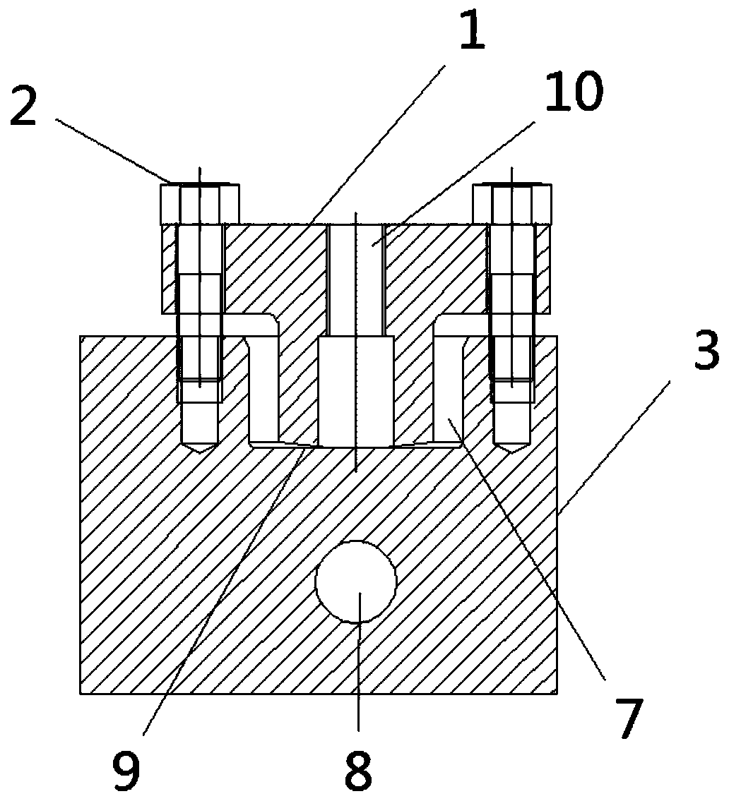
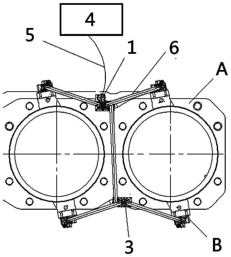
[0029] see figure 1 , the pumping tool 1 is provided with a hydraulic oil passage, which communicates with the upper surface of the pumping tooling 1 through the quick interface 10 , and the lower surface of the pumping tooling 1 is a sealing spherical surface 9 . The pumping tooling 1 is fixedly connected to the distribution block 3 of the gas hydraulic drive pipeline through the connecting bolt 2, and is in close contact with the distribution block 3 by means of the sealing spherical surface 9. The spherical surface size of the sealing spherical surface 9 is determined according to the The allocation block 3 is determined and processed. The distribution block 3 is provided with a leak detection hole, a hydraulic oil inlet 7 and a plurality of hydraulic oil outlets 8, the hydraulic oil inlet 7 is connected to the hydraulic oil outlets 8, and the leak detection hole is connected with a leak detection plug. see figure 2 , the distribution block 3 is installed on the cylinder...


PUM


Abstract

The invention provides a device and a method for testing the sealing performance of a natural gas hydraulic drive pipeline of a diesel engine. The natural gas hydraulic drive pipeline comprises a distribution block and a hydraulic drive pipe, the distribution block comprises a leakage detection hole, a hydraulic oil inlet and a plurality of hydraulic oil outlets, the hydraulic oil inlet communicates with the plurality of hydraulic oil outlets, and the plurality of hydraulic oil outlets are respectively connected with intake valves of various cylinders of the diesel engine through the hydraulicdrive pipe. The device is characterized in that a pumping tool is hermetically connected to the hydraulic oil inlet of the distribution block, the pumping tool is connected with a mobile hydraulic pump truck through a hydraulic hose and a quick connector thereof, the mobile hydraulic pump truck provides hydraulic oil corresponding to a detection pressure, the hydraulic oil enters each intake valve, and whether the natural gas hydraulic drive pipeline has leakage is checked by observing the leakage conditions of the leakage detection hole on the distribution block and the hydraulic drive pipe.According to the device provided by the invention, the inspection of the sealing performance of the pipeline is performed in the assembly phase, thereby avoiding operation difficulty caused by the narrow space on an experiment table, and achieving the effects of improving the operating efficiency and ensuring the installation quality.

Description

technical field [0001] The invention relates to a manufacturing process of a marine low-speed diesel engine low-pressure dual-fuel main engine, in particular to a device and method for testing the tightness of a natural gas hydraulic drive pipeline of a diesel engine, and belongs to the technical field of marine diesel engines. Background technique [0002] With the gradual entry of international emission regulations into the TIII era, in order to solve the emission problem of marine low-speed diesel engines, a dual-fuel main engine that can use diesel and natural gas at the same time has been introduced. At the same time, a natural gas pipeline system has been added to the main engine. The natural gas pipeline system controls the gas to enter the cylinder liner through the intake valves on both sides of the cylinder liner. The intake valve is driven by hydraulic oil of about 200bar. The stem opens, and the valve stem is closed again by spring return after the hydraulic oil ...

Claims


Application Information

Patent Timeline
Patent Type & Authority Applications(China)
IPC IPC(8): G01M3/02
CPCG01M3/025
Inventor 黄晗笑江军张飞黄润辉
Owner CSSC MES DIESEL
Learn More