
Optical fiber fault point auxiliary positioning and online optical fiber auxiliary fiber aligning device and application

An optical fiber fault and auxiliary positioning technology, which is applied in the field of optical fiber communication, can solve problems such as differences between drawings and actual optical fibers, easy to break optical fibers by mistake, and complicated procedures, so as to improve maintenance efficiency and quality, improve repair speed, and simple operation Effect

Pending Publication Date: 2020-01-17
TIANSHENGQIAO BUREAU CSG EHV POWER TRANSMISSION CO
View PDF0 Cites 0 Cited by
  • Summary
  • Abstract
  • Description
  • Claims
  • Application Information

AI Technical Summary

Problems solved by technology

[0003] For example, for a 24-core 50km optical cable line in normal operation, the two sides are welded on the ODF frame, and there will be about 20 times of fusion points in the middle. During construction, it is easy to weld wrong tubes and wrong cores, resulting in differences between the drawings and the actual optical fibers. Accurately find the abnormal operation and maintenance of certain optical fibers in the intermediate splice box
For example, to check the corresponding relationship between a certain fiber at a splice point and the 5th port of the A-side ODF, in the past, an optical time domain reflectometer was connected to the 5th port of the A-side ODF for light emission testing, and the corresponding fiber core predicted at the splice point Cut off, and determine whether the predicted optical fiber corresponds to the fifth port of the A-side ODF through the change of the distance measurement length of the optical time domain reflectometer. If the distance measurement length of the optical time domain reflectometer does not change, it is not corresponding, and you need to select again Other fiber cores are cut and continue to search, so it is easy to accidentally cut off other normal operating fibers, and the cut fibers need to be re-made and spliced, and the process is complicated
[0004] Another example: the 24-core 50km optical cable line running in the urban pipeline was interrupted by mice. Currently, the optical time domain reflectometer test is used to judge that it is interrupted at a distance of 23km from the A-side ODF frame. Level deviation, it is still difficult to find

Method used


Image

  • Optical fiber fault point auxiliary positioning and online optical fiber auxiliary fiber aligning device and application
  • Optical fiber fault point auxiliary positioning and online optical fiber auxiliary fiber aligning device and application
  • Optical fiber fault point auxiliary positioning and online optical fiber auxiliary fiber aligning device and application

Examples


Embodiment Construction

[0037] In order to make the purpose, technical solutions and advantages of the embodiments of the present invention clearer, the technical solutions in the embodiments of the present invention will be clearly and completely described below in conjunction with the drawings in the embodiments of the present invention. Obviously, the described embodiments It is a part of embodiments of the present invention, but not all embodiments. The components of the embodiments of the invention generally described and illustrated in the figures herein may be arranged and designed in a variety of different configurations.

[0038] Accordingly, the following detailed description of the embodiments of the invention provided in the accompanying drawings is not intended to limit the scope of the claimed invention, but merely represents selected embodiments of the invention. Based on the embodiments of the present invention, all other embodiments obtained by persons of ordinary skill in the art wi...


PUM


Abstract

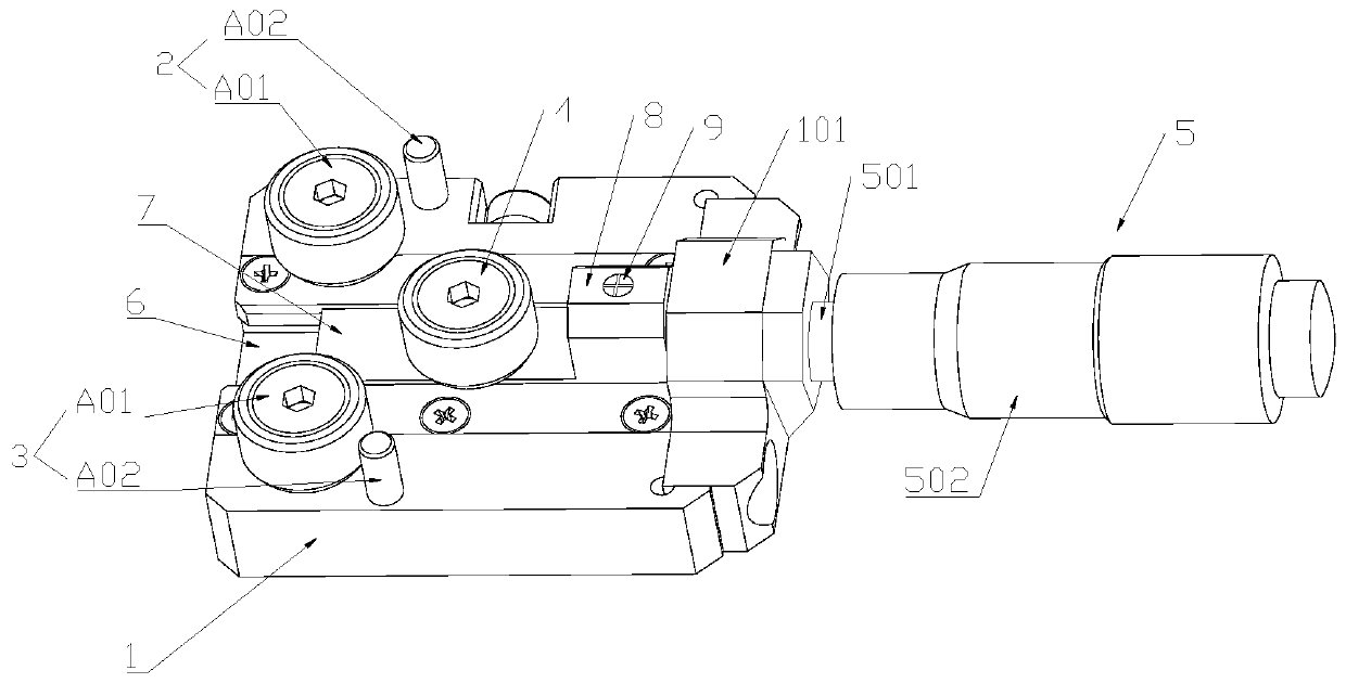
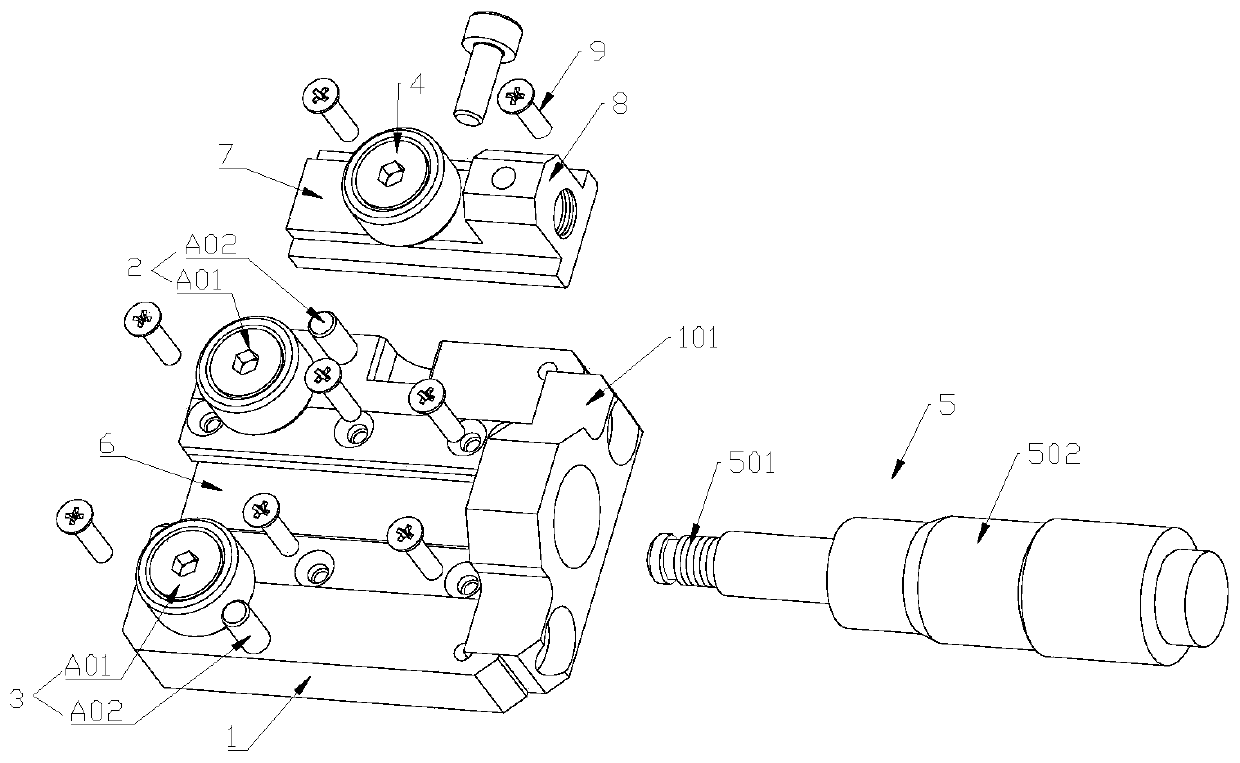
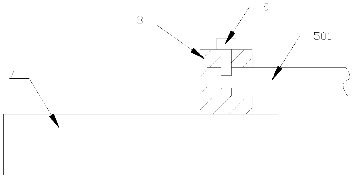
The invention relates to the technical field of optical fiber communication. The invention discloses an optical fiber fault point auxiliary positioning and online optical fiber auxiliary fiber aligning device. The device comprises an operation table, a first positioning fixing piece, a second positioning fixing piece, a movable fixing piece and an operation part, the first positioning fixing piece, the second positioning fixing piece and the movable fixing piece are all arranged on the operation table. The movable fixing piece is movably arranged between the first positioning fixing piece andthe second positioning fixing piece; the optical fiber can wind around the first positioning fixing piece, the movable fixing piece and the second positioning fixing piece, and the position of the movable fixing piece on the operation table can be changed under the telescopic action of the operation part so that the curvature radius of the optical fiber connected among the three fixing pieces canbe changed. According to the invention, the macro-bending degree of the optical fiber reference point is changed on line, so that the optical path attenuation change of the optical fiber occurs at thereference point position, the specific fiber core and position where attenuation occurs are quickly determined through the test comparison of the optical time domain reflectometer, the purpose of searching the fiber and a fault point is achieved, and the maintenance benefit and quality of an optical cable line are improved.

Description

technical field [0001] The invention belongs to the technical field of optical fiber communication, and in particular relates to an optical fiber fault point auxiliary positioning and online optical fiber auxiliary fiber alignment device and application. Background technique [0002] At present, it is very difficult to align the optical fibers and determine the fault points of the optical fibers on the optical cable lines. [0003] For example, for a 24-core 50km optical cable line in normal operation, the two sides are welded on the ODF frame, and there will be about 20 times of fusion points in the middle. During construction, it is easy to weld wrong tubes and wrong cores, resulting in differences between the drawings and the actual optical fibers. It is difficult to accurately find the abnormal operation and maintenance of some optical fibers in the intermediate splice box. For example, to check the corresponding relationship between a certain fiber at a splice point an...

Claims


Application Information

Patent Timeline
IPC IPC(8): H04B10/071H04B10/077G01M11/00G02B6/38
CPCG01M11/3109G02B6/38G02B6/3887H04B10/071H04B10/0771
Inventor 梁昌奇张正江岑韬林礼华姚发兴吴建山
Owner TIANSHENGQIAO BUREAU CSG EHV POWER TRANSMISSION CO
Learn More