Bidirectional traction device of knee joint

A two-way traction and knee joint technology, which is applied in the field of medical devices, can solve problems such as inconvenience, uneven force, and human injury, and achieve the effect of ensuring therapeutic effect, convenient adjustment, and not easy to loosen

Pending Publication Date: 2020-01-21
上海市静安区闸北中心医院
View PDF3 Cites 0 Cited by
  • Summary
  • Abstract
  • Description
  • Claims
  • Application Information

AI Technical Summary

Problems solved by technology

However, the device in this patent is located on one side and does not have symmetry. When it is used for continuous traction, it will cause the problem of uneven force, which will affect the curative effect and may even directly lead to traction failure. It is equipped with an adjustable fixing frame. , which increases the burden on one side of the patient. When the patient moves, the Kirschner nail may not be able to bear the moment generated by the entire device, which may cause damage to the human body, leading to treatment failure or even medical accidents. The traction force application device and connector, It does not have the pressure indication function, so that the doctor does not know how much force is applied, which causes great inconvenience

Method used


Image

  • Bidirectional traction device of knee joint
  • Bidirectional traction device of knee joint
  • Bidirectional traction device of knee joint

Examples


Embodiment 1

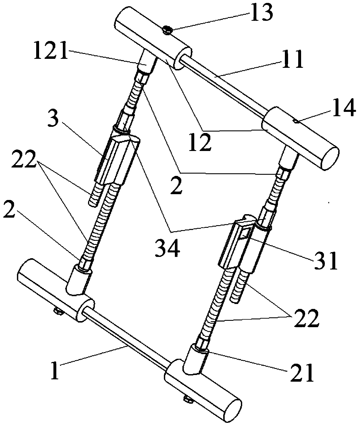
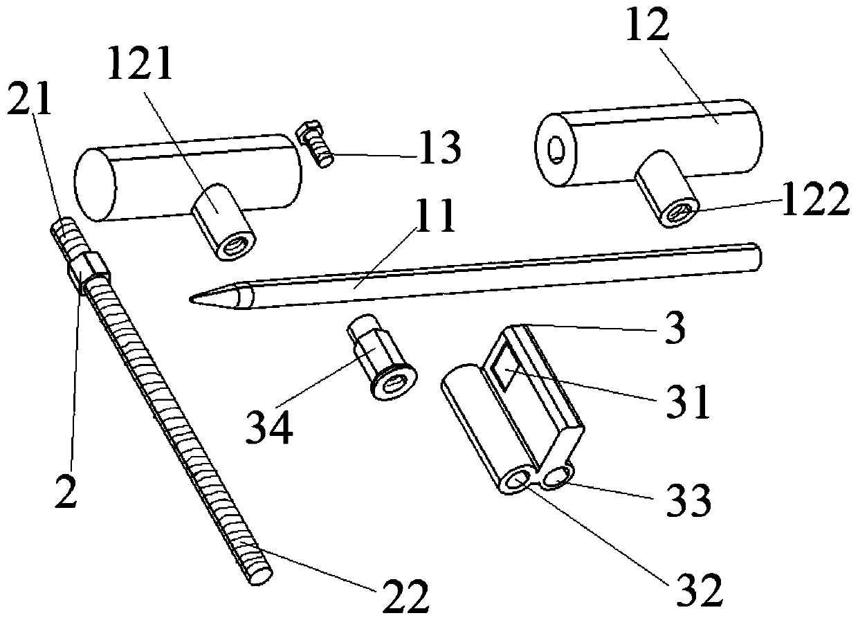
[0038] Please see attachedfigure 1 , with figure 1 A three-dimensional schematic diagram of a knee joint two-way traction device of the present invention. A two-way traction device for the knee joint, including two traction rods 1, four connecting rods 2, and two lifting connectors 3; please refer to the attached figure 2 , attached image 3 , with figure 2 It is a three-dimensional schematic diagram of each basic component of a knee joint two-way traction device of the present invention from the lower left perspective; image 3 It is a three-dimensional schematic view from the upper right perspective of each basic component of a knee joint two-way traction device of the present invention. The drawbar 1 is a cylindrical structure, and also includes a Kirschner wire 11, two Kirschner wire sleeves 12, and two fastening bolts 13, and the Kirschner wire sleeve 12 is made of medical hard PVC material It is a hollow cylindrical structure with one end opening, and there are bol...

Embodiment 2

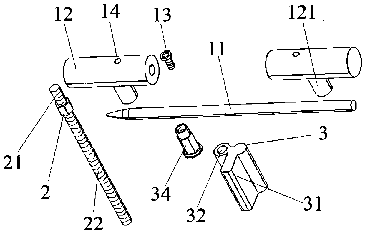
[0042] Please see attached Figure 6 , with Figure 6 It is a three-dimensional schematic diagram of another knee joint two-way traction device of the present invention. A knee joint two-way traction device, comprising two traction rods 1, four connecting rods 2, and two lifting connectors 3; the traction rod 1 is a cylindrical structure, and also includes Kirschner wires 11, two Kirschner wires Sleeve 12, two fastening bolts 13, described Kirschner wire sleeve 12 is the hollow cylindrical structure of one end opening, is also provided with bolt hole 14 on it; Please refer to attached figure 1 , the Kirschner wire sleeve 12 can be detachably connected to both ends of the Kirschner wire 11, the fastening bolt 13 is adapted to the bolt hole 14, and the Kirschner wire 11 can pass through the fastening The bolt 13 is fastened with the Kirschner wire sleeve 12; the Kirschner wire sleeve 12 is provided with a first connecting portion 121, and the first connecting portion 121 is an...


PUM


Abstract

The invention belongs to the technical field of medical equipment, and relates to a bidirectional traction device of a knee joint. The bidirectional traction device comprises a plurality of traction rods, a plurality of connecting rods and a plurality of lifting connectors; the traction rods are composed of kirschner wire sleeve tubes, kirschner wires and fastening bolts; and the traction rods arevertically and detachably connected with the connecting rods, the adjacent connecting rods can be movably connected through the lifting connectors, and the lifting connectors are composed of pressuresensors with displays, sleeving-connecting sections, pressure grooves and pressure applying nuts. The height of the lifting connectors is adjusted by the pressure applying nuts to achieve the effectof adjusting pressure, and the traction rods can penetrate through bones. The bidirectional traction device has the advantages of simple operation, stable structure, safe, reliable, controllable traction, continuous and stable traction effect, two-way traction and no need to actively combat traction.

Description

technical field [0001] The invention relates to the technical field of medical instruments, in particular to a knee joint two-way traction device. Background technique [0002] At present, the clinically available tibial tuberosity traction system is an important auxiliary means for the treatment of fractures around the knee joint. After the fracture occurs, the broken end of the fracture is pulled by the muscles or tendons attached to it, causing angulation, shortening, rotation, separation, and other displacements, which may easily cause blood vessel and nerve compression, and even damage. For patients with severe soft tissue injury or many underlying diseases, emergency surgical reduction and fixation are not suitable. At this time, tibial tubercle traction is particularly important. By placing a 4.0mm diameter Steiner wire transversely at the level of the tibial tubercle for traction, the contracted muscles and tendons can be reinstated, so that the displaced fracture ...

Claims


Application Information

Patent Timeline
Patent Type & Authority Applications(China)
IPC IPC(8): A61B17/66
CPCA61B17/6441A61B17/6458A61B17/66
Inventor 郑川玉满毅
Owner 上海市静安区闸北中心医院
Why Eureka
Try Eureka