Horizontal pushing type firefighting blank door

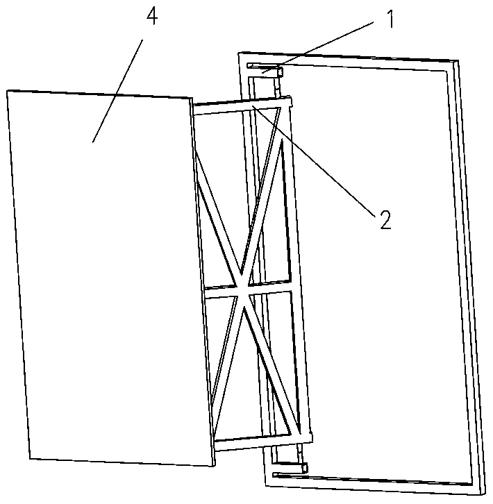
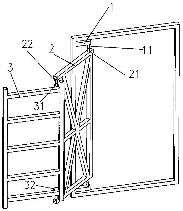
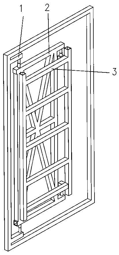
A flat-push, fire-fighting technology, used in windows/doors, door/window applications, door/window accessories, etc., can solve problems such as the influence of the thickness of the decorative surface layer, and achieve the effect of small occupied space, simple structure and convenient use.

Active Publication Date: 2020-01-21
DECORATION CO LTD OF CHINA CONSTR 3RD ENG BUREAU
9 Cites 0 Cited by

AI-Extracted Technical Summary

Problems solved by technology

[0003] The invention provides a horizontal push type fire trap door, which is provided with three layers of connecting rods, connected by a rotating shaft, and ov...

Method used

[0030] Further, the inside of the outer frame is provided with horizontal struts. The middle frame and the outer frame are equipped with support rods to ensure the structural strength, stability and deformation resistance.
[0031] As shown in Figure 1, further, the second ...

Abstract

The invention discloses a horizontal pushing type firefighting blank door which comprises first-layer connecting rods, second-layer connecting rods, third-layer connecting rods and a door plank. The two first-layer connecting rods are symmetrically arranged in the vertical direction, the two second-layer connecting rods are symmetrically arranged in the vertical direction, the two third-layer connecting rods are symmetrically arranged in the vertical direction, and the first-layer connecting rods, the second-layer connecting rods and the third-layer connecting rods are arranged in a layered manner from the two sides to the middle portion. The upper side first-layer connecting rod is fixed to a door frame, and the bottom face of the outer end of the upper side first-layer connecting rod isprovided with a first rotating shaft. The upper side second-layer connecting rod is located below the upper side first-layer connecting rod and is connected with a first rotating shaft through a second rotating shaft at the inner end of the upper side second-layer connecting rod, and the bottom face of the outer end of the upper side second-layer connecting rod is provided with a third rotating shaft. The upper side third-layer connecting rod is connected with the third rotating shaft through a fourth rotating shaft which is arranged at the inner end of the upper side third-layer connecting rod. The upper side third-layer connecting rod and the lower side third-layer connecting rod are connected through vertical connecting rods to form an outer frame, and the door plank is arranged on theouter side face of the outer frame. By means of the horizontal pushing type firefighting blank door, the blank door is firstly drawn to disengage from the door frame through rotating and moving of theconnecting rods, then horizontal pushing is conducted to avoid the position, and it is ensured that the opening angle of the firefighting blank door meets the requirements; and the horizontal pushingtype firefighting blank door has the beneficial effects that the structure is simple, use is convenient, the occupied space is small, and the opening angle is large.

Application Domain

Door/window applicationsWing arrangements +2

Technology Topic

Structural engineeringMechanical engineering +1

Image

  • Horizontal pushing type firefighting blank door
  • Horizontal pushing type firefighting blank door
  • Horizontal pushing type firefighting blank door

Examples

  • Experimental program(1)

Example Embodiment

[0023] The technical solutions in the embodiments of the present invention will be clearly and completely described below in conjunction with the accompanying drawings of the specification. Obviously, the described embodiments are only a part of the embodiments of the present invention, rather than all the embodiments. Based on the embodiments of the present invention, all other embodiments obtained by those of ordinary skill in the art without creative work shall fall within the protection scope of the present invention.
[0024] In the description of this patent, it should be understood that the terms "center", "upper", "lower", "front", "rear", "left", "right", "vertical", "horizontal", The orientation or positional relationship indicated by "top", "bottom", "inner", "outer", etc. are based on the orientation or positional relationship shown in the drawings, and are only for the convenience of describing the patent and simplifying the description, rather than indicating or implying The device or element referred to must have a specific orientation, be constructed and operated in a specific orientation, and therefore cannot be understood as a limitation of this patent.
[0025] Such as figure 1 , 2 , 3, a flat push type fire concealed door, including a first-layer connecting rod 1, a second-layer connecting rod 2, a three-layer connecting rod 3 and a door panel 4, the first-layer connecting rod 1, the second-layer connecting rod 2 and There are two three-layer connecting rods 3 arranged symmetrically up and down, and they are arranged from both sides to the middle part; the upper layer connecting rod 1 is arranged horizontally, and its inner end is fixed on the door frame, and the bottom surface of the outer end is provided with a rotating shaft 11 The upper two-layer connecting rod 2 is arranged horizontally, located below the first-layer connecting rod 1, and its inner end surface is provided with two rotating shafts 21, the two rotating shafts 21 are connected to the rotating shaft 11, and the upper second layer connecting rod 2 is outside The bottom surface of the end is provided with a rotating shaft 22; the upper three-layer connecting rod 3 is arranged horizontally, located below the second-layer connecting rod 2, and its inner end surface is provided with a rotating shaft 31, which is connected to the rotating shaft three 22. The three-layer connecting rods 3 are connected by vertical connecting rods to form an outer frame, and the door panel 4 is arranged on the outer surface of the outer frame; the upper and lower spacing of the two second-layer connecting rods 2 is smaller than the height of the door panel 4.
[0026] In the present invention, when the door panel 4 is opened, through the rotation of the inner and outer ends of the two-layer connecting rod 2 and the movement of the rods, the door panel 4 is moved back and forth and pulled out of the door frame, and the total thickness of the decorative materials on both sides is exceeded. The rotation of the connecting rod 3 and the second-layer connecting rod 2 pushes the door panel 4 to the outside of the door frame by moving in the left and right direction, completing the opening of the hidden door and ensuring the opening and closing angle.
[0027] Such as figure 2 , 3 The heights of the three-layer connecting rods are different. The upper and lower heights of the second-layer connecting rod 2 and the third-layer connecting rod 3 are both smaller than the height of the door panel 4, and the door frame does not interfere with the movement of the second-layer connecting rod 2.
[0028] Such as Figure 5 As shown, further, the rotating shaft 431 is connected to the three-layer connecting rod 3 through an adapter rod 32, the adapter rod 32 is vertically arranged on the inner surface of the three-layer connecting rod 3, and the upper rotating shaft 31 is arranged at On the upper surface of the adapter rod 32; the inner surface of the three-layer connecting rod 3 and the outer surface of the second-layer connecting rod 2 are located on the same vertical surface.
[0029] Such as Figure 4 As shown, further, vertical connecting rods are provided between the two-layer connecting rods 2 to form a middle frame, and supporting rods are arranged inside the middle frame, and the supporting rods include diagonal bracing rods and horizontal bracing rods.
[0030] Further, horizontal struts are provided inside the outer frame. The middle frame and the outer frame are provided with support rods to ensure the structural strength, stability and resistance to deformation.
[0031] Such as figure 1 As shown, further, the second-layer connecting rod 2 is arranged directly under the first-layer connecting rod 1 and on the same vertical plane. The thickness of the decorative layer is effective, and the superimposed arrangement can effectively reduce space occupation and save space.
[0032] Further, the internal structures of the outer frame and the middle frame are all connected by welding, the rotating shaft 11 is welded to the first-layer connecting rod 1, and the rotating shaft two 21 and the rotating shaft three 22 are welded to the second-layer connecting rod 2. Connected, the rotating shaft 431 and the three-layer connecting rod 3 are welded and connected.
[0033] Further, the first-layer connecting rod 1, the second-layer connecting rod 2 and the third-layer connecting rod 3 are galvanized square links. Preferably, the first-layer connecting rod 1, the second-layer connecting rod 2 and the third-layer connecting rod 3 adopt 40*40mm galvanized square links.
[0034] Furthermore, the first-layer connecting rod 1 and the second-layer connecting rod 2 of different lengths are arranged according to the thickness of the decorative layer to ensure that the hidden door can be opened normally and its opening angle.
[0035] Further, the door panel 4 is screwed to the outer frame, and the first-layer connecting rod 1 is screwed to the door frame.
[0036] For those skilled in the art, it is obvious that the present invention is not limited to the details of the foregoing exemplary embodiments, and the present invention can be implemented in other specific forms without departing from the spirit or basic characteristics of the present invention. Therefore, from any point of view, the embodiments should be regarded as exemplary and non-limiting. The scope of the present invention is defined by the appended claims rather than the foregoing description, and therefore it is intended to fall within the claims. All changes within the meaning and scope of the equivalent elements of are included in the present invention, and any reference signs in the claims should not be regarded as limiting the involved claims.

PUM

no PUM

Description & Claims & Application Information

We can also present the details of the Description, Claims and Application information to help users get a comprehensive understanding of the technical details of the patent, such as background art, summary of invention, brief description of drawings, description of embodiments, and other original content. On the other hand, users can also determine the specific scope of protection of the technology through the list of claims; as well as understand the changes in the life cycle of the technology with the presentation of the patent timeline. Login to view more.

Similar technology patents

Body condition measuring device

InactiveUS20050234351A1simple structure
Owner:DENSO CORP

Magnetic cooling apparatus and control method thereof

ActiveUS20130180263A1simple structure
Owner:SAMSUNG ELECTRONICS CO LTD

Dual-Drivetrain of Power-Assist Vehicle

InactiveUS20100181130A1enhance uphill momentumsimple structure
Owner:CHOU WEN CHENG

Classification and recommendation of technical efficacy words

  • Simple structure
  • Easy to use

Sharing system for air-conditioning coat

InactiveCN107440179ASimple structureeasy to wear
Owner:QINGDAO HAIER AIR CONDITIONER GENERAL CORP LTD

Feeding device of sorter of batteries plate

InactiveCN101357717ASimple structurecooperate well
Owner:NANJING NORMAL UNIVERSITY

Emergency parachuting device and method for multiple-rotor unmanned aerial vehicle

InactiveCN103895870Aavoid aircraft crashSimple structure
Owner:SOUTH CHINA AGRI UNIV +1

Laser assisted total joint arthroplasty

InactiveUS20090234360A1easy to use
Owner:ALEXANDER VLADIMIR

Enclosure for a portable hemodialysis system

ActiveUS20090114582A1easy to use
Owner:DEKA PROD LLP
Why Eureka
Try Eureka