
Aircraft energy demand refined analysis method and equipment

An analysis method and demand technology, applied in computer-aided design, design optimization/simulation, geometric CAD, etc., can solve the problems of poor iteration, long time, and redundant content, and achieve the effect of accurate analysis results and simple operation.

Pending Publication Date: 2020-01-21
SHENYANG AIRCRAFT DESIGN INST AVIATION IND CORP OF CHINA
View PDF23 Cites 1 Cited by
  • Summary
  • Abstract
  • Description
  • Claims
  • Application Information

AI Technical Summary

Problems solved by technology

The existing aircraft energy demand analysis method is based on the data collection and integration and then presented in the form of a written table. The table integration and result analysis take a long time and cannot match the rapidity required by the subsequent design. This is mainly due to the following aspects The disadvantages are caused by: a. Using the peak power value or rated power value as the indicator of the power demand input of the load equipment lacks the dynamic power characteristics of the load equipment, such as sudden addition, sudden unloading, and the embodiment of pulse power characteristics, which affects the follow-up design on the instantaneous power Judgment of demand, which requires a detailed description of dynamic power characteristics; b. Most of the current analysis methods are only based on written form, and the analysis data is mostly displayed in the form of a large number of tables, which is too long to present the analysis conclusion intuitively and quickly; c. The current analysis method is poorly iterative, affected by the way the table is presented, it is impossible to quickly switch a certain variable or a certain group of variables to compare and observe the analysis results

Method used


Image

  • Aircraft energy demand refined analysis method and equipment

Examples


Embodiment Construction

[0041] In order to make the purpose, technical solution and advantages of the application more clear, the technical solution in the embodiment of the application will be described in more detail below in conjunction with the drawings in the embodiment of the application. In the drawings, the same or similar reference numerals denote the same or similar elements or elements having the same or similar functions throughout. The described embodiments are some, but not all, embodiments of the application. The embodiments described below by referring to the figures are exemplary, and are intended to explain the present application, and should not be construed as limiting the present application. Based on the embodiments in this application, all other embodiments obtained by persons of ordinary skill in the art without creative efforts fall within the protection scope of this application. Embodiments of the present application will be described in detail below in conjunction with th...


PUM


Abstract

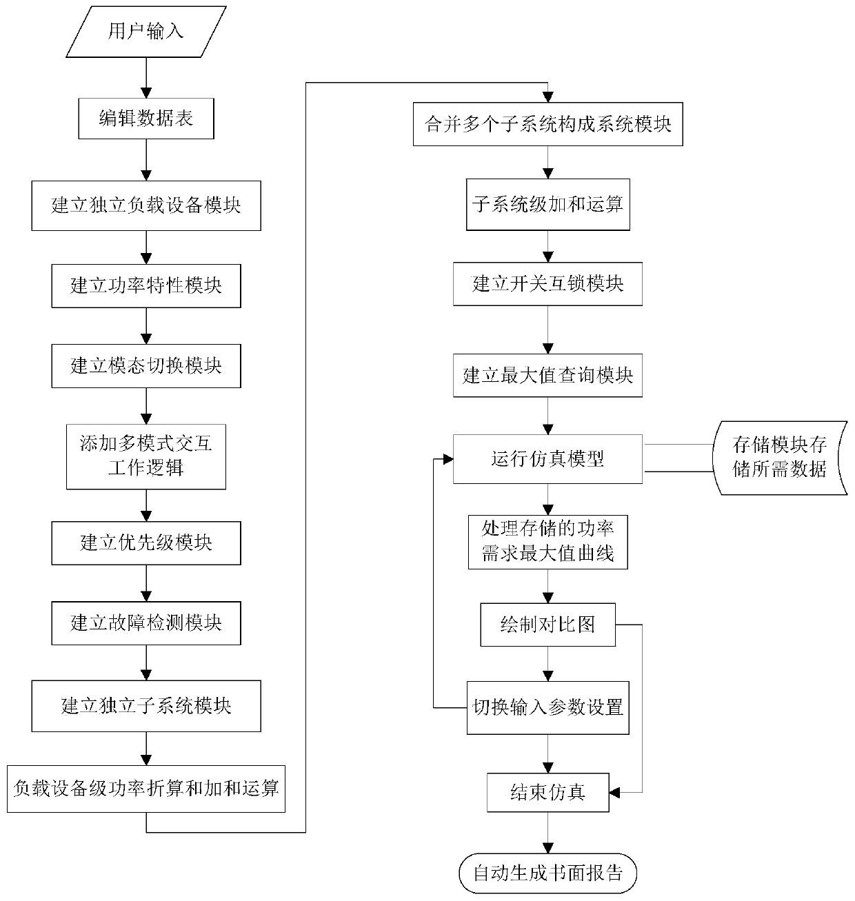
The invention belongs to the field of energy system design, and particularly relates to an aircraft energy demand refined analysis method and equipment. The method comprises the steps of acquiring user input parameters, and establishing a database according to the user input parameters; 2, constructing a subsystem model according to the database, and calculating a subsystem-level total power demand; 3, combining the subsystem models to form a system model, and calculating a system-level total power demand; and 4, operating the system model to obtain a simulation result, and generating a written report. The dynamic power characteristics of the load equipment can be reflected in a final analysis result graph, and the analysis result is more accurate and reliable; the simulation model is simple and convenient to operate, repeatable and high in iteration; the simulation model can count required power in a short time and draw a system-level power requirement curve, a system-level total power requirement curve and a power requirement maximum value square wave curve comparison graph of each single-class energy requirement type, so that the analysis time is saved, and the efficiency is improved.

Description

technical field [0001] The application belongs to the field of energy system design, and in particular relates to a refined analysis method and equipment for aircraft energy demand. Background technique [0002] The analysis of aircraft energy demand is an important reference for the design of aircraft energy system and the design of energy system energy equipment and load equipment. The existing aircraft energy demand analysis method is based on the data collection and integration and then presented in the form of a written table. The table integration and result analysis take a long time and cannot match the rapidity required by the subsequent design. This is mainly due to the following aspects The disadvantages are caused by: a. Using the peak power value or rated power value as the indicator of the power demand input of the load equipment lacks the dynamic power characteristics of the load equipment, such as sudden addition, sudden unloading, and the embodiment of pulse ...

Claims


Application Information

Patent Timeline
Patent Type & Authority Applications(China)
IPC IPC(8): G06F30/15G06F30/20G06F119/06
Inventor 张庆超毕雯燕王鹤
Owner SHENYANG AIRCRAFT DESIGN INST AVIATION IND CORP OF CHINA
Learn More