
Video decoding apparatus based on self-adaptive video decoding method

A video decoding and self-adaptive technology, applied in separation methods, chemical instruments and methods, digital video signal modification, etc., can solve problems such as reduced service life, damaged electronic components of decoders, and complicated use of decoders.

Inactive Publication Date: 2020-01-21
深圳市优立信科技有限公司
View PDF9 Cites 7 Cited by
  • Summary
  • Abstract
  • Description
  • Claims
  • Application Information

AI Technical Summary

Problems solved by technology

[0003] The decoder is generally composed of relays, communication chips and fuses. Since the decoder needs to decode and output a large amount of data during operation, the operating frequency of the decoder is relatively fast, which in turn generates a lot of heat on the decoder. Existing decoders dissipate heat directly through fans. Since the electronic components inside the decoder are more precise, when dissipating heat, the dust in the air will be adsorbed on its surface due to air convection, which will affect the work of the decoder. In addition, sometimes the place where the decoder is used is more complicated, which makes the decoder vulnerable to impact and vibration, which damages the electronic components inside the decoder and reduces its service life

Method used


Image

  • Video decoding apparatus based on self-adaptive video decoding method
  • Video decoding apparatus based on self-adaptive video decoding method
  • Video decoding apparatus based on self-adaptive video decoding method

Examples


Embodiment Construction

[0028] In order to make the above objects, features and advantages of the present invention more comprehensible, specific implementations of the present invention will be described in detail below in conjunction with the accompanying drawings. In the following description, numerous specific details are set forth in order to provide a thorough understanding of the present invention. However, the present invention can be implemented in many other ways different from those described here, and those skilled in the art can make similar improvements without departing from the connotation of the present invention, so the present invention is not limited by the specific implementations disclosed below.

[0029] It should be noted that when an element is referred to as being “fixed” to another element, it can be directly on the other element or there can also be an intervening element. When an element is referred to as being "connected to" another element, it can be directly connected ...


PUM


Abstract

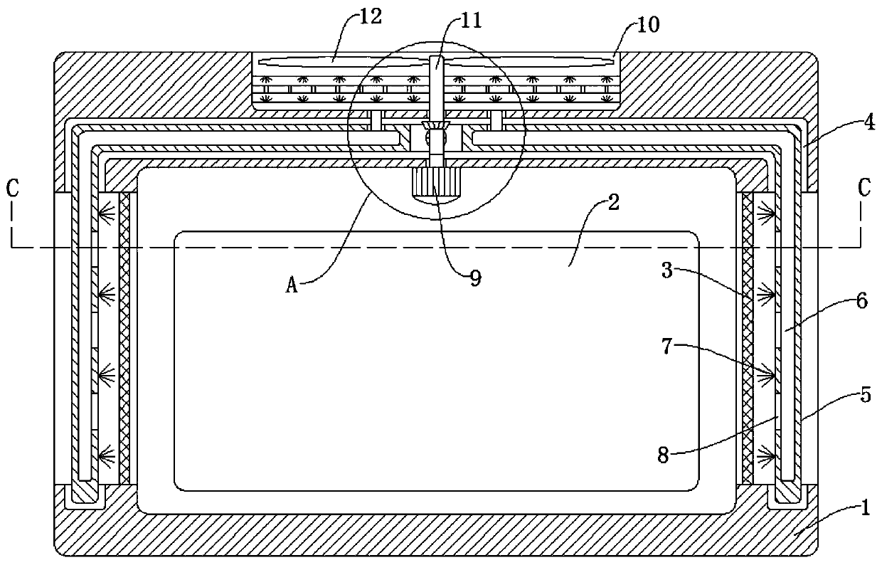
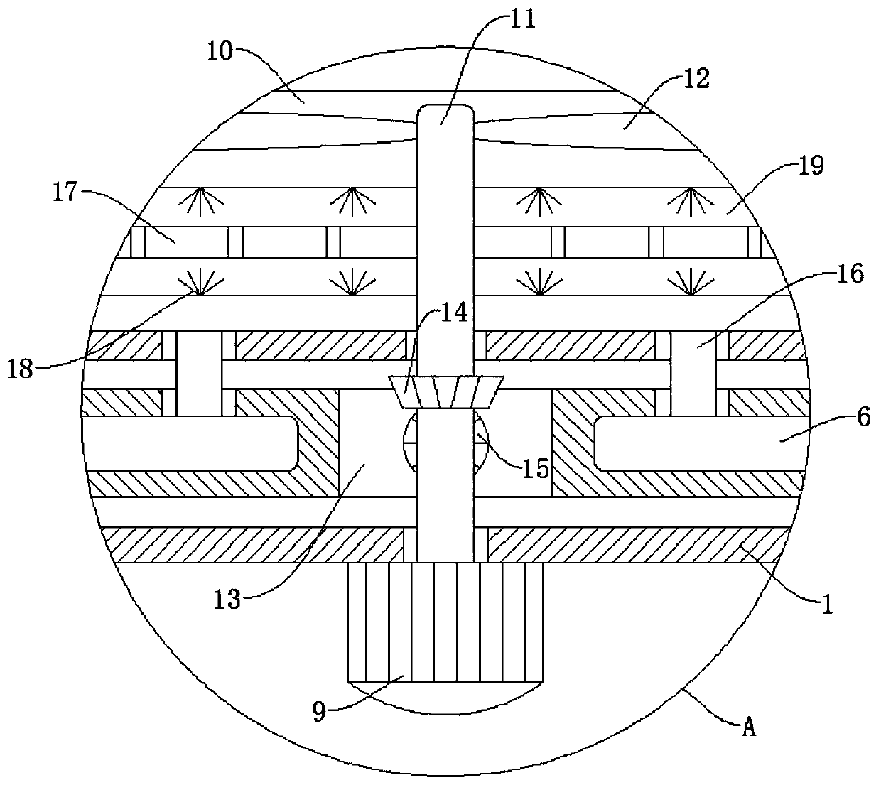
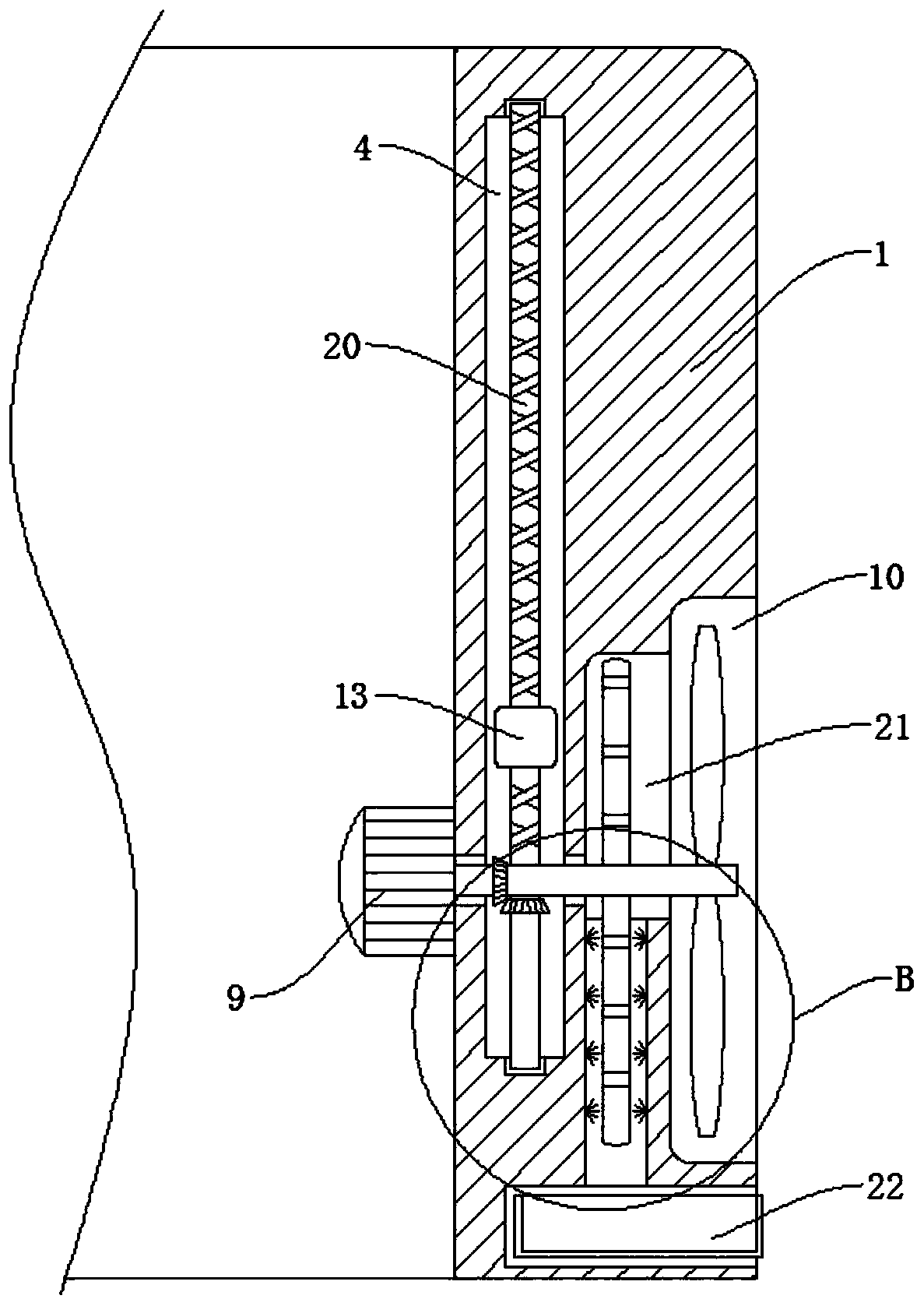
The invention discloses video decoding equipment based on a self-adaptive video decoding method. The video decoding equipment comprises an equipment shell, a decoder is arranged in the equipment shell, frame openings are formed in the opposite side walls of the equipment shell, a filter screen is fixedly connected to the side walls of the frame openings, a first cleaning device for cleaning the filter screen is installed on the equipment shell, and a damping device for damping the equipment shell is installed on the equipment shell. A first bevel gear, a second bevel gear, a reciprocating leadscrew, a sliding block and an L-shaped plate are arranged; the sliding block can drive the L-shaped plate to slide up and down on the inner wall of the U-shaped groove; first bristles on the side wall of the L-shaped plate are used for cleaning dust on the side wall of the filter screen; by arranging the rotating shaft, the negative-pressure impeller, the filter plate and the dust suction pipe, negative pressure exists in the circular groove when the negative-pressure impeller rotates quickly, so that dust scraped off from the filter screen is sucked into the first semicircular groove throughthe dust suction holes and the dust suction pipe, and the dust scraped off from the filter screen is prevented from flying everywhere.

Description

technical field [0001] The present invention relates to the technical field of video decoding equipment, in particular to a video decoding equipment based on an adaptive video decoding method. Background technique [0002] A video decoding device is a device capable of compressing or decompressing digital video. It mainly consists of a decoder in a structural video decoding device. The decoder converts data encoded files into analog video and audio signals. [0003] The decoder is generally composed of relays, communication chips and fuses. Since the decoder needs to decode and output a large amount of data during operation, the operating frequency of the decoder is relatively fast, which in turn generates a lot of heat on the decoder. Existing decoders dissipate heat directly through fans. Since the electronic components inside the decoder are more precise, when dissipating heat, the dust in the air will be adsorbed on its surface due to air convection, which will affect th...

Claims


Application Information

Patent Timeline
Patent Type & Authority Applications(China)
IPC IPC(8): H04N19/44H05K5/02H05K7/20B01D46/48B01D46/10B01D46/00F16F15/04
CPCH04N19/44H05K5/0217H05K7/20181H05K7/20172B01D46/10B01D46/48F16F15/04B01D46/681
Inventor 唐家宝
Owner 深圳市优立信科技有限公司
Learn More