
Arm supporting frame used for hand surgery

A support frame and surgical technology, applied in the direction of surgery, operating table, medical science, etc., can solve the problems of inconvenient replacement and cleaning, unfavorable effective surgical operation, unfavorable operation efficiency, etc., to achieve easy replacement and cleaning, easy disassembly of bandages, and improved The effect of surgical efficiency

Inactive Publication Date: 2020-01-24
JINAN THE THIRD HOSPITAL
View PDF5 Cites 1 Cited by
  • Summary
  • Abstract
  • Description
  • Claims
  • Application Information

AI Technical Summary

Problems solved by technology

[0002] The patent number is CN 204723339 U, which is called a patent of arm support frame for hand surgery. There are several ventilation holes on the arm support plate, and it is easy to sweat and evaporate when the ambient temperature is high during the operation, but there are still some disadvantages in this device. First, one end of the strap is fixedly connected to the U-shaped arm support plate. When it is contaminated, it is inconvenient to replace and clean. At the same time, the free ends of multiple bandages need to be connected or disassembled separately, which is not conducive to improving operation efficiency; in addition, the U-shaped arm support plate is fixedly installed on the inner sleeve rod. , when the wound to be operated on is evenly distributed around the arm, the downward position of the wound is not conducive to effective surgical operation, but it is not convenient and practical to reopen the bandage and turn the arm angle. In view of this, we propose an arm support frame for hand surgery to solve the above problems

Method used


Image

  • Arm supporting frame used for hand surgery
  • Arm supporting frame used for hand surgery
  • Arm supporting frame used for hand surgery

Examples


Embodiment Construction

[0016] The following will clearly and completely describe the technical solutions in the embodiments of the present invention with reference to the accompanying drawings in the embodiments of the present invention. Obviously, the described embodiments are only some, not all, embodiments of the present invention. Based on the embodiments of the present invention, all other embodiments obtained by persons of ordinary skill in the art without making creative efforts belong to the protection scope of the present invention.

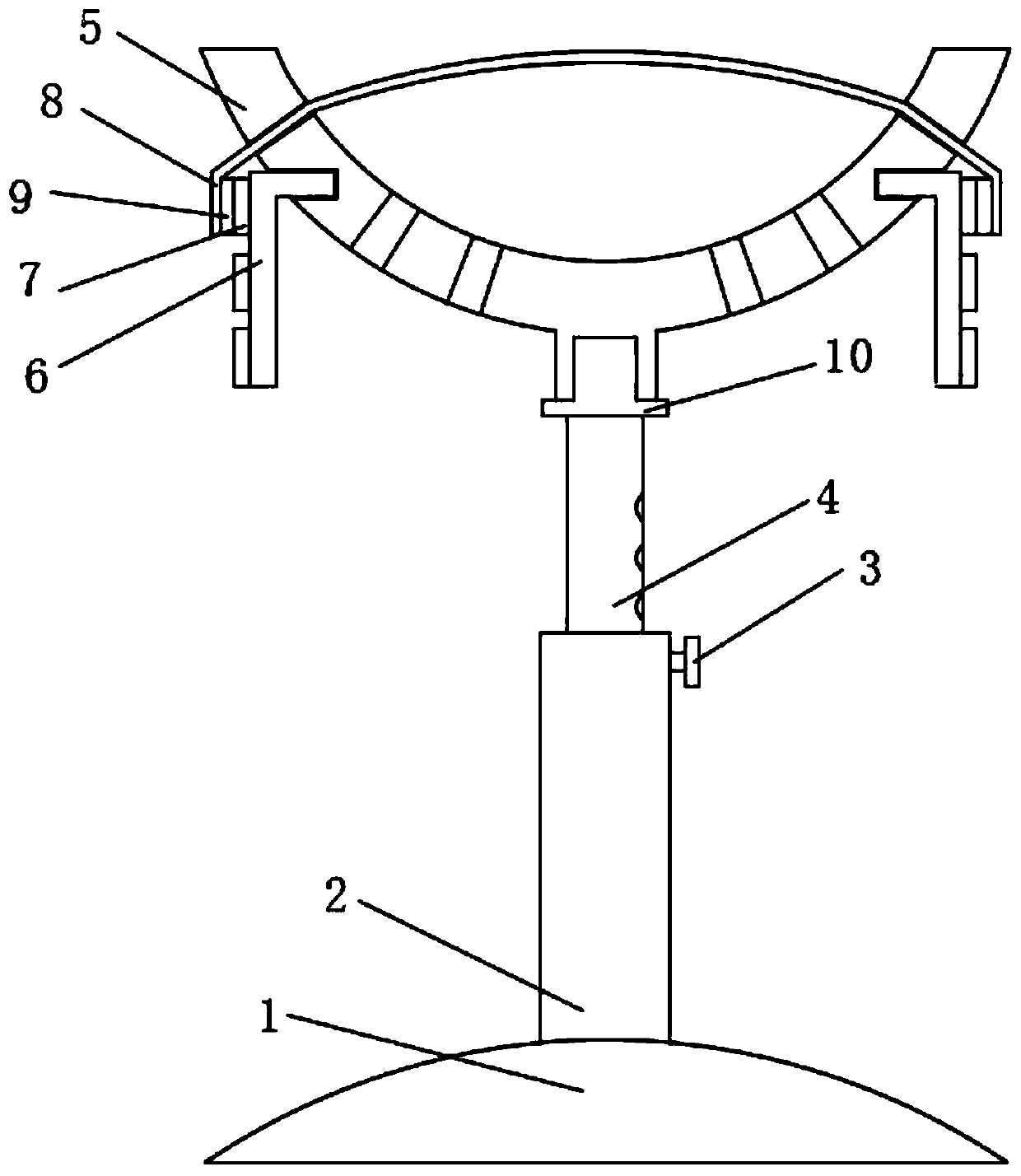
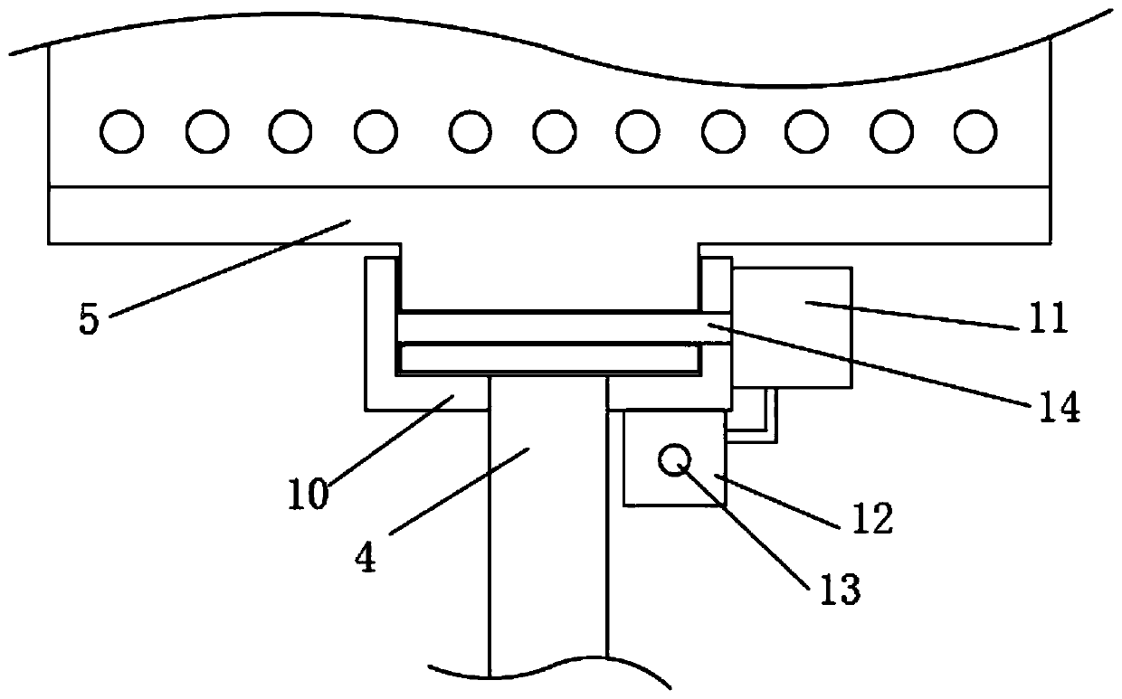
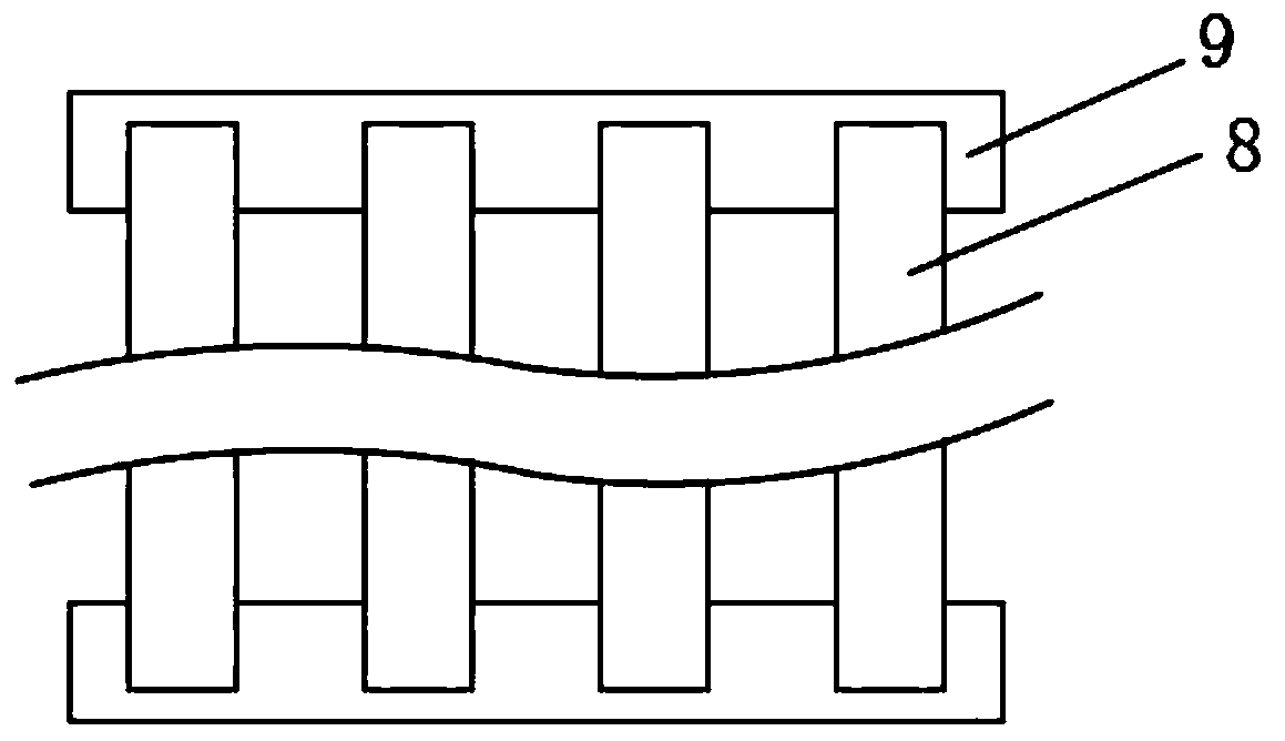
[0017] see Figure 1-3 , an arm support frame for hand surgery, comprising a table suction cup 1, an outer rod cover 2, a positioning pin 3, an inner rod cover 4 and a U-shaped arm support plate 5, the top of the inner rod cover 4 is movably connected with a U-shaped arm support plate 5 , the top end of the inner rod sleeve 4 is fixedly installed with a mounting cover 10, and the mounting cover 10 is U-shaped with the opening facing upwards. A motor 11 is fix...


PUM


Abstract

The invention discloses an arm supporting frame used for hand surgery. The arm supporting frame comprises a table board sucking disk, an outer rod cover, a positioning pin, an inner rod cover and a U-shaped arm supporting plate, wherein the top end of the inner rod cover is movably connected with the U-shaped arm supporting plate; two sides of the bottom end of the U-shaped arm supporting plate are independently provided with a positioning insertion plate; the U-shaped arm supporting plate is provided with a binding belt group, and the binding belt group consists of binding belts which are inlongitudinal array distribution; and two ends of the binding belt group are independently provided with an auxiliary hook and loop fastener. The binding belts which penetrate through two sides of theU-shaped arm supporting plate are arranged on the U-shaped arm supporting plate, two ends of each binding belt are independently provided with the auxiliary hook and loop fastener, the bottom end of the U-shaped arm supporting plate is provided with the positioning insertion plate with main hook and loop fasteners corresponding to the auxiliary hook and loop fasteners, so that the binding belts can be easily installed and disassembled so as to be convenient replacement and cleaning. By use of the arm supporting frame, the U-shaped arm supporting plate is set into a rotation type along the inner rod cover, and rotates to an electronic control type so as to be favorable for regulating an arm angle according to a wound position, and the arm supporting frame is convenient and quick and is favorable for improving operation efficiency.

Description

technical field [0001] The invention relates to the technical field of medical equipment, in particular to an arm support frame for hand surgery. Background technique [0002] The patent number is CN 204723339 U, which is called a patent of arm support frame for hand surgery. There are several ventilation holes on the arm support plate, and it is easy to sweat and evaporate when the ambient temperature is high during the operation, but there are still some disadvantages in this device. First, one end of the strap is fixedly connected to the U-shaped arm support plate. When it is contaminated, it is inconvenient to replace and clean. At the same time, the free ends of multiple bandages need to be connected or disassembled separately, which is not conducive to improving operation efficiency; in addition, the U-shaped arm support plate is fixedly installed on the inner sleeve rod. , when the wound to be operated on is evenly distributed around the arm, the downward position of...

Claims


Application Information

Patent Timeline
Patent Type & Authority Applications(China)
IPC IPC(8): A61B90/14A61G13/12
CPCA61G13/1235A61B90/14
Inventor 王建尹成国
Owner JINAN THE THIRD HOSPITAL
Learn More