Facing sand processing system for water-permeable bricks

A processing system and technology of permeable bricks, applied in grain processing and other fields

Pending Publication Date: 2020-01-24
贞丰县恒山建材有限公司
0 Cites 0 Cited by

AI-Extracted Technical Summary

Problems solved by technology

[0004] The purpose of the present invention is to: propose a surface sand processing system for permeable bricks, which is used to overcome the above deficiencies, to screen out materials with a balanced size, and to perform multiple screenings under the action of the screen to obtain uni...

Abstract

Disclosed is a facing sand processing system for water-permeable bricks. The facing sand processing system comprises a cylindrical stirring bucket, a rotary shaft I is arranged around the central axisinside the cylindrical stirring bucket, and spiral blades are fixed to the rotary shaft I; one end of the rotary shaft I is connected with a motor I, a rotary shaft II which has the same direction asthe cylindrical stirring bucket is arranged above the cylindrical stirring bucket, and a plurality of connecting rods are arranged on the rotary shaft II; the rotary shaft II is connected with the motor I through a belt pulley, a conical sand inlet is connected to one end of the cylindrical stirring bucket, and the outer surface of the conical sand inlet is connected with a motor II located belowthe conical sand inlet through a gear belt; the circumferential face of the cylindrical stirring bucket is provided with a primary filtering net, a slant groove-shaped outlet is connected to the other end of the cylindrical stirring bucket, the lower position of the groove-shaped outlet is connected with a first conveying belt, and a hopper matched with the cylindrical stirring bucket is arrangedunder the cylindrical stirring bucket. By means of the facing sand processing system, multistage screening can be achieved, and the system can also run in an assembly line, so that the efficiency isimproved.

Application Domain

Grain treatments

Technology Topic

Electric machineryRotational axis +8

Image

  • Facing sand processing system for water-permeable bricks

Examples

  • Experimental program(1)

Example Embodiment

[0016] The technical solutions in the embodiments of the present invention are clearly and completely described below in conjunction with the accompanying drawings. Apparently, the described embodiments are only a part of the embodiments of the present invention, not all of them.
[0017] In describing the present invention, it should be understood that the terms "upper", "lower", "front", "rear", "left", "right", "top", "bottom", "inner", " The orientation or positional relationship indicated by "outside", etc. is based on the orientation or positional relationship shown in the drawings, and is only for the convenience of describing the present invention and simplifying the description, rather than indicating or implying that the referred device or element must have a specific orientation, so as to Specific orientation configurations and operations, therefore, are not to be construed as limitations on the invention.
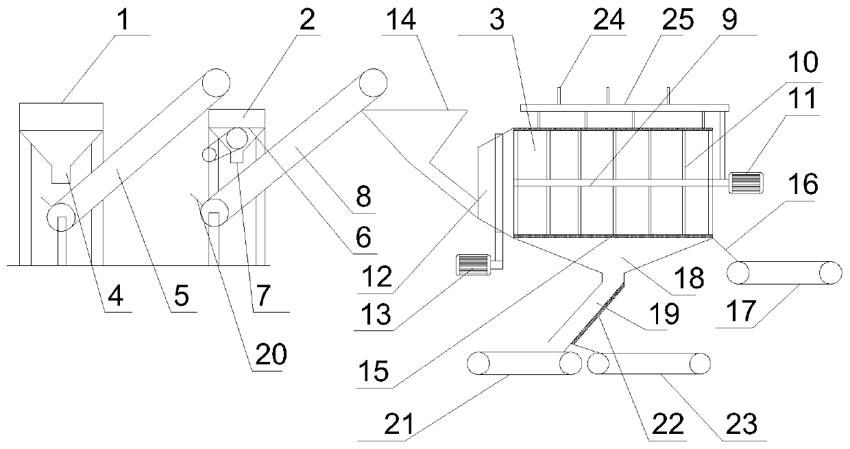
[0018] Referring to the accompanying drawings, the surface sand processing system for permeable bricks includes a hopper-type feeding device 1, a jaw crusher 2 and a cylindrical mixing tank 3. A discharge port I4 is provided under the hopper-type feeding device 1, and the The lower end of the discharge port I4 is provided with an inclined first conveyor belt 5, one end of the first conveyor belt 5 is connected to the discharge port I4, and the other end of the first conveyor belt 5 is provided with a jaw crusher 2. The jaw crusher 2 is provided with a feed port I6, and the jaw crusher 2 is provided with a discharge port II7 connected to the jaw crusher 2, and the discharge port II7 is connected to the inclined second conveyor belt 8 Connected at one end, the inner centerline of the cylindrical mixing bucket 3 is provided with a rotating shaft I9, on which a helical blade 10 is fixed, and one end of the rotating shaft I9 is ​​connected to the motor I11, and the top of the cylindrical mixing bucket 3 There is a rotating shaft II 25 in the same direction as the cylindrical mixing bucket 3, and a plurality of connecting rods 24 are arranged on the rotating shaft II 25, and the rotating shaft II and the motor I11 are connected through a pulley, and the cylindrical mixing bucket 3 One end is connected with a conical sand inlet 12, the outer surface of the conical sand inlet 12 is connected with the motor II13 located below the conical sand inlet 12 through a gear belt, and the other end of the conical sand inlet 12 is provided with a hopper I14, the hopper I14 is connected to the other end of the second conveyor belt 8, the peripheral surface of the cylindrical mixing bucket 3 is provided with a primary filter 15, and the other end of the cylindrical mixing bucket 3 is connected to an inclined groove Outlet 16, a third conveyor belt 17 is connected below the trough outlet 16, a hopper II 18 matching the cylindrical mixing drum 3 is provided directly below the cylindrical mixing drum 3, and the lower end of the hopper II 18 is connected with an inclined Hopper outlet 19.
[0019] A valve is provided at the outlet I4 of the hopper-type feeding device 1 .
[0020] A baffle 20 is provided at the upper ends of the first conveyor belt 5 and the second conveyor belt 8 .
[0021] A fourth conveyor belt 21 is connected to the end of the hopper outlet 19 .
[0022] The lower surface of the hopper outlet 19 is provided with a secondary filter screen 22 for screening.
[0023] Directly below the hopper outlet 19 is connected to the fifth conveyor belt located directly below the hopper outlet 19 through an inclined trough-shaped groove.
[0024] The rotation direction of the motor I11 is opposite to that of the motor II13.
[0025] The cylindrical mixing barrel 3 is provided with a protective cover connected with the hopper.
[0026] Before use, ensure that the motors on the conveyor belt are running normally. When in use, put the raw materials into the hopper-type feeding device 1, open the valve on the outlet I4, and let the raw materials enter the hopper-type feeding device 1, the first Conveyor belt 5, jaw crusher 2, hopper I14, cylindrical mixing barrel 3, when the raw material enters the jaw crusher 2 and completes crushing, enters the cylindrical mixing barrel 3 to complete the screening, and between the spiral blade 10 and the rotating shaft I9 Under the action, the fine raw materials will fall into the hopper II 18 through the primary filter screen 15 on the peripheral surface of the cylindrical mixing barrel 3, and the coarse particles will enter the third conveyor belt 17 through the groove outlet 16. When the fine raw materials enter After the hopper II 18, the secondary filter screen 22 can also be used to screen again to obtain materials with ideal sizes. The provided rotating shaft II 25 and connecting rod 24 can beat the primary filter screen 15 during operation, so that the raw materials stuck in the primary filter screen 15 will drop without accumulation or blockage.
[0027] 1- Hopper type feeding device, 2- Jaw crusher, 3- Cylindrical mixing barrel, 4- Outlet Ⅰ, 5- First conveyor belt, 6- Inlet Ⅰ, 7- Outlet Ⅱ, 8-second conveyor belt, 9-rotating shaft Ⅰ, 10-spiral blade, 11-motor Ⅰ, 12-conical sand inlet, 13-motor Ⅱ, 14-hopper Ⅰ, 15-primary filter, 16- Groove outlet, 17-third conveyor belt, 18-hopper II, 19-hopper outlet, 20-baffle, 21-fourth conveyor belt, 22-secondary filter, 23-fifth conveyor belt, 24-connection Rod, 25-axis of rotation II.
[0028] The above is only a preferred embodiment of the present invention, but the scope of protection of the present invention is not limited thereto, any person familiar with the technical field within the technical scope disclosed in the present invention, according to the technical solution of the present invention Any equivalent replacement or change of the inventive concepts thereof shall fall within the protection scope of the present invention.

PUM

no PUM

Description & Claims & Application Information

We can also present the details of the Description, Claims and Application information to help users get a comprehensive understanding of the technical details of the patent, such as background art, summary of invention, brief description of drawings, description of embodiments, and other original content. On the other hand, users can also determine the specific scope of protection of the technology through the list of claims; as well as understand the changes in the life cycle of the technology with the presentation of the patent timeline. Login to view more.
Why Eureka
Try Eureka