A planar sliding propulsion method of a shield machine

A shield machine and plane technology, which is applied in earth-moving drilling, mining equipment, tunnels, etc., can solve the problems of low construction efficiency, bracket damage, and low reuse rate.

Inactive Publication Date: 2021-07-06
HENAN POLYTECHNIC UNIV +1
View PDF11 Cites 0 Cited by
  • Summary
  • Abstract
  • Description
  • Claims
  • Application Information

AI Technical Summary

Problems solved by technology

The publication number is CN102337900A, which discloses a method for empty pushing of a circular bedding type shield machine. The device is provided with a bracket at the bottom of the shield machine, and two rows of vertical jacks are arranged on both sides, and the horizontal jack transmits force through the reaction device and the bracket. , the horizontal jack pushes the shield machine forward on the bracket, and then starts the vertical jack to lift the shield machine, the horizontal jack shrinks, pushes the bracket forward, shrinks the vertical jack and the shield machine falls on the bracket Repeat the above Pushing forward, because the above device is in contact with the ground, the forward movement of the bracket and the sliding friction on the ground will easily cause damage to the bracket, and the shield machine is generally as high as thousands of tons. The bracket can be moved forward only when the machine is fully lifted away from the bracket. This method has low construction efficiency, low reuse rate, high consumption and high cost in actual engineering.

Method used


Image

  • A planar sliding propulsion method of a shield machine
  • A planar sliding propulsion method of a shield machine
  • A planar sliding propulsion method of a shield machine

Examples


Embodiment 1

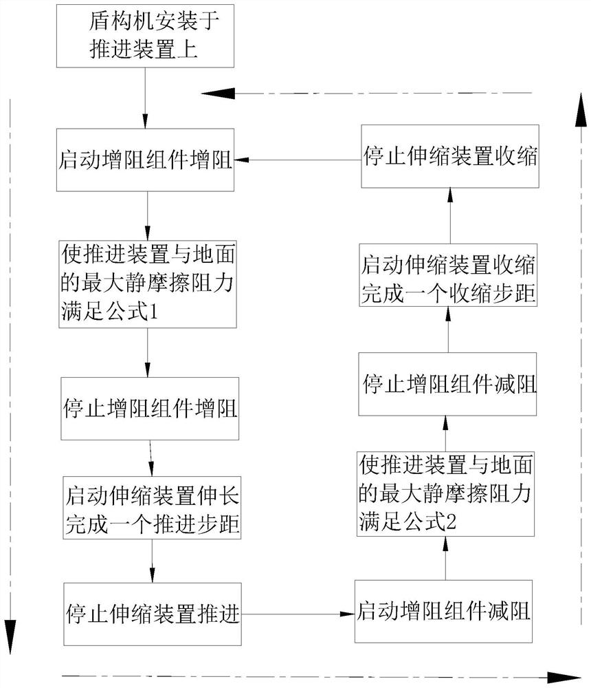
[0061] Such as figure 1 As shown, the present invention provides a planar sliding propulsion method of a shield machine, utilizing such as Figure 2-8 Shown propulsion device realizes; Described propulsion method is:

[0062] When the telescopic device 6 is elongated and advanced, the resistance increasing assembly 4 is started to increase the resistance, so that the acceleration of the shield machine 10 relative to the seat plate 2 is greater than the acceleration of the support frame 1 relative to the ground;

[0063] When the telescopic device 6 shrinks, the resistance increasing assembly 4 is activated to reduce the resistance, so that the acceleration of the shield machine 10 relative to the seat plate 2 is smaller than the acceleration of the support frame 1 relative to the ground.

[0064] Specifically, the mass sum of the shield machine 10 and the expansion device 6 is M d , the mass of supporting frame 1 is M zc , the mass of seat plate 2 is M zb , the mass of sli...

Embodiment 2

[0079] This embodiment also provides a planar sliding propulsion device for the shield machine, which can realize continuous propulsion and improve propulsion efficiency.

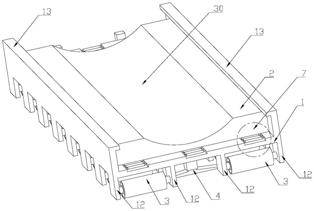
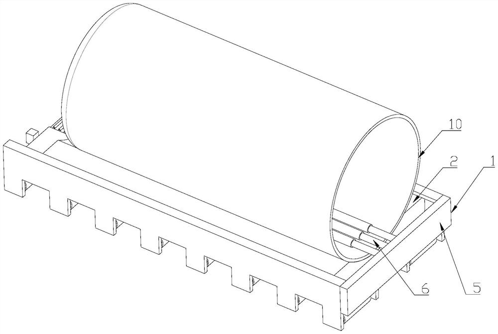
[0080] The technical solution adopted by the present invention is to combine Figure 2~3 As shown, a shield machine planar sliding propulsion device is provided, including a support frame 1, which is arranged on the upper side of the support frame 1, a seat plate 2 for supporting the shield machine 10, and a plurality of slides arranged on the lower side of the support frame 1. Shifting assembly 3, a plurality of resistance increasing assemblies 4, and a reaction force device 5 arranged at the tail end of the support frame 1, one end of the shield machine 10 is provided with a telescopic device 6, and the telescopic device 6 is a hydraulic push cylinder. The push cylinder provides thrust and pull for the shield machine. The hydraulic push cylinder 6 is supported by the reaction force device 5 to realize th...


PUM


Abstract

The present invention aims at overcoming at least one defect of the prior art, and provides a planar sliding propulsion method of a shield machine. The propulsion method is: when the telescopic device is stretched and propelled, the resistance increasing component is activated to increase the resistance, so that the shield The acceleration of the shield machine relative to the seat plate is greater than the acceleration of the support frame relative to the ground; when the telescopic device shrinks, the resistance increasing component is activated to reduce the resistance, so that the acceleration of the shield machine relative to the seat plate is smaller than the acceleration of the support frame relative to the ground. The propulsion method of the present invention only needs to adjust the resistance of the resistance-increasing component to realize the maximum static friction force between the propulsion device and the ground during different propulsion processes, and the adjustment of the height of the resistance-increasing component can realize the sliding of the resistance-increasing component The force conversion between components is easy to operate, and the wear on the bottom of the propulsion device is reduced, and the service life is improved.

Description

technical field [0001] The invention relates to the technical field of tunnel engineering, in particular to a planar sliding propulsion method of a shield machine. Background technique [0002] In recent years, with the rapid development of cities, the construction of urban subways has developed rapidly, and the construction of urban rail transit has become more and more popular. Shield excavation is now the main method of urban subway construction, but when encountering some complex geology, other construction methods are required. When constructing a tunnel, when the shield machine reaches the excavated tunnel, it is necessary to empty push the shield machine through the excavated tunnel section. In order to ensure that the shield machine is smoothly pushed through the excavated tunnel section, the concrete guide platform in the excavated tunnel is used as the shield body support, and the steel rail laid on the guide platform is used as the shield body walking track. As t...

Claims


Application Information

Patent Timeline
Patent Type & Authority Patents(China)
IPC IPC(8): E21D9/06
CPCE21D9/0621
Inventor 郭佳奇黄山秀檀俊坤徐冲黄鑫
Owner HENAN POLYTECHNIC UNIV
Why Eureka
Try Eureka