
A light-transmitting box-type transformer

A box-type transformer and transformer technology, applied in the field of transformers, can solve the problems of long interval time, failure of casing sealing, deterioration of thermal stability, etc. Effect

Active Publication Date: 2022-07-22
JIANGSU HAIKAI ELECTRIC
View PDF0 Cites 0 Cited by
  • Summary
  • Abstract
  • Description
  • Claims
  • Application Information

AI Technical Summary

Problems solved by technology

The position of the sealing structure moved by the user during installation and maintenance should be carefully restored to the original sealing state. In addition, it is closely related to the sealing, that is, to ensure that the surface of the porcelain sleeve is intact, and cracks and scars are not allowed on the surface of the porcelain sleeve. The reason is that porcelain Once cracks and scars appear on the surface of the sleeve, it means that the porcelain sleeve basically loses its own mechanical strength, its heat resistance and insulation performance will be greatly reduced, and the thermal stability will deteriorate, which will easily cause transformer failure
[0011] However, in the actual inspection process, the inspectors can only observe the cracks on the outer surface of the transformer bushing. It is difficult for the inspectors to find the aging cracks inside the transformer bushing. Longer, during the non-maintenance time, after the aging and cracking inside the transformer bushing, the crack expands to the outer surface of the bushing, resulting in the failure of the sealing of the whole bushing, and it is too late for the next maintenance

Method used


Image

  • A light-transmitting box-type transformer
  • A light-transmitting box-type transformer
  • A light-transmitting box-type transformer

Examples


Embodiment 1

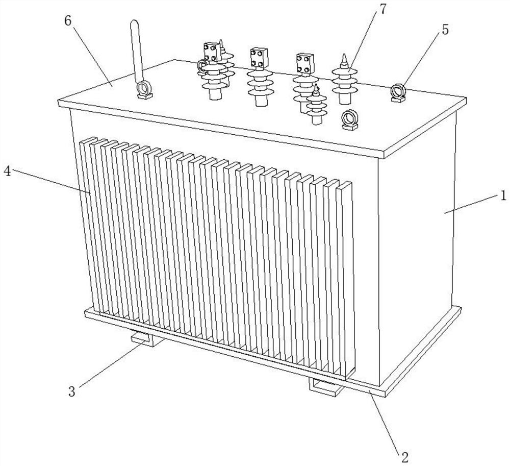
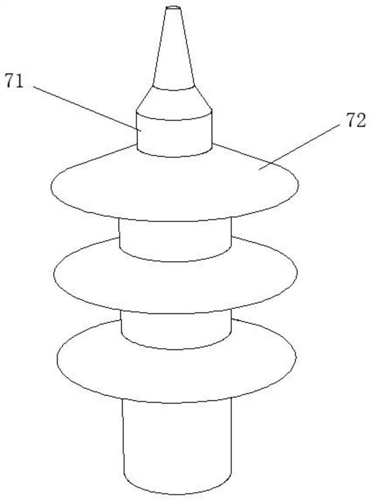
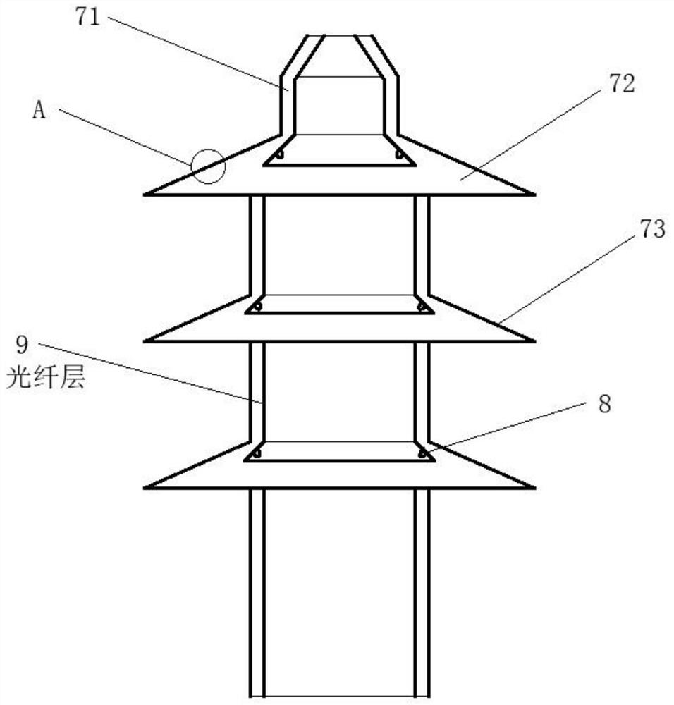
[0045] see figure 1 , a light-transmitting box-type transformer, comprising a transformer body 1 with a top plate 6 and a bottom plate 2 respectively installed at the upper and lower ends, the upper end of the transformer body 1 is connected with a bushing 7, and the top plate 6 is drilled with a bushing 7. The side end of the transformer body 1 is fixedly connected with a plurality of evenly distributed heat dissipation fins 4, which promotes the heat dissipation of the transformer body 1, ensures the stable operation performance of the transformer body 1, and is not prone to frequent failures due to its high internal temperature. The mounting feet 3 are connected to avoid direct contact between the bottom plate 2 at the bottom of the transformer body 1 and the ground, which is convenient for handling. For example, a forklift can be inserted into the gap between the bottom plate 2 and the mounting feet 3 for transportation. The upper end of the top plate 6 is fixedly connected...


PUM


Abstract

The invention discloses a light-transmitting box-type transformer, belonging to the field of transformers. A light-transmitting box-type transformer comprises a transformer body with a top plate and a bottom plate respectively installed at the upper and lower ends, the upper end of the transformer body is connected with a bushing, the bushing It includes an insulating tube body and a plurality of insulating umbrellas, and an actinic layer is connected to the inner side wall of the insulating umbrella. The surface of the insulating umbrella is wrapped with a light-transmitting layer. The light-transmitting layer includes a healing layer and a transparent layer, and a transparent self-healing body is arranged in the healing layer. In this scheme, an actinic layer and a light-transmitting layer are respectively arranged on the inner wall and outer surface of the transformer bushing, and a healing layer is arranged in the light-transmitting layer. The transparent self-healing body fills the gap to achieve the self-sealing effect. In addition, the light beam emitted by the actinic layer will be emitted from the gap through the transparent self-healing body, making it easier for maintenance personnel to observe the crack position, so that maintenance measures can be taken in time. .

Description

technical field [0001] The invention relates to the field of transformers, and more particularly, to a light-transmitting box-type transformer. Background technique [0002] Transformer is a device that uses the principle of electromagnetic induction to change the AC voltage. The main components are the primary coil, the secondary coil and the iron core (magnetic core). [0003] Box-type transformers (usually referred to as "box-type transformers") centrally design traditional transformers in box-type shells, with small size, light weight, low noise, low loss, and high reliability, and are widely used in residential quarters, commercial centers, light Stations, airports, factories and mines, enterprises, hospitals, schools and other places. As a complete set of power distribution equipment, box-type transformers are organically combined with transformers, high-voltage voltage control equipment, and low-voltage voltage control equipment. The basic principle is that through ...

Claims


Application Information

Patent Timeline
Patent Type & Authority Patents(China)
IPC IPC(8): H01F27/06H01F27/22H01F27/32C09J175/14
CPCH01F27/324H01F27/22H01F27/06C09J175/14
Inventor 戴敏
Owner JIANGSU HAIKAI ELECTRIC
Learn More