
Distribution transformer with iron core replacement function

A technology for distribution transformers and iron cores, applied in transformer/inductor shells, transformer/inductor cooling, transformer/inductor cores, etc., can solve transformer core load loss and impedance voltage increase, inconvenient iron core Disassembly, time-consuming and other problems, to achieve the effect of improving moisture-proof ability, convenient disassembly and replacement, and good moisture-proof effect

Inactive Publication Date: 2020-01-24
江苏龙创电气有限公司
View PDF15 Cites 4 Cited by
  • Summary
  • Abstract
  • Description
  • Claims
  • Application Information

AI Technical Summary

Problems solved by technology

[0003] For the existing dry-type transformer core, the moisture-proof treatment is mainly to add gaskets at the bottom of the transformer to isolate moisture, but in a humid environment, the moisture inside the air is relatively large, causing moisture to enter the core body and cause corrosion. A large amount of heat energy will be generated when the transformer iron core works for a period of time, resulting in a large increase in the load loss and impedance voltage of the transformer iron core, which affects the use, and the general transformer iron core is installed through the iron core seat and fixed by a large number of bolts and nuts. It is inconvenient to disassemble the iron core during maintenance and replacement, and it is easy to spend a lot of time when installing and fixing

Method used


Image

  • Distribution transformer with iron core replacement function
  • Distribution transformer with iron core replacement function
  • Distribution transformer with iron core replacement function

Examples


Embodiment Construction

[0028] In order to make the purpose, features and advantages of the present invention more obvious and understandable, the technical solutions in the embodiments of the present invention will be clearly and completely described below in conjunction with the accompanying drawings in the embodiments of the present invention. Obviously, the following The described embodiments are only some, not all, embodiments of the present invention. Based on the embodiments of the present invention, all other embodiments obtained by persons of ordinary skill in the art without making creative efforts belong to the protection scope of the present invention.

[0029] The technical solutions of the present invention will be further described below in conjunction with the accompanying drawings and through specific implementation methods.

[0030] In the description of the present invention, it should be understood that the orientations or positional relationships indicated by the terms "upper", "...


PUM


Abstract

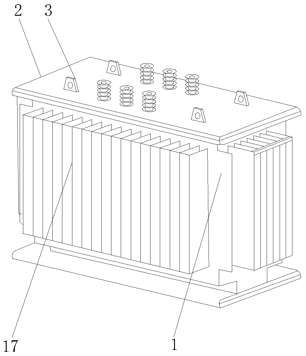
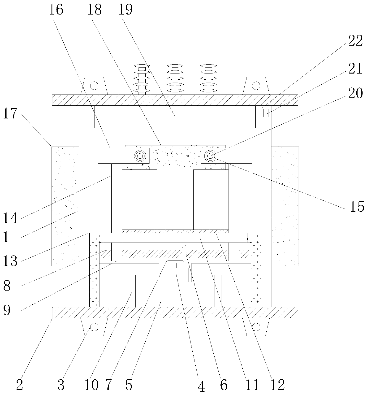
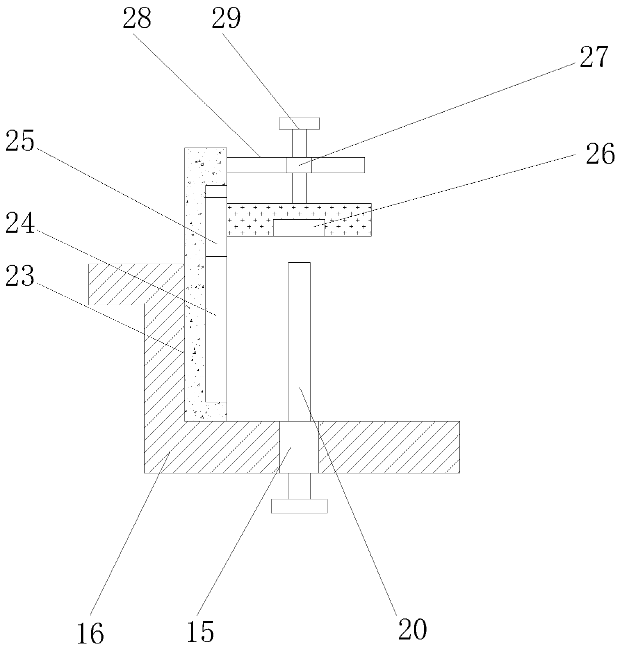
The invention discloses a distribution transformer with an iron core replacement function. The distribution transformer comprises a shell, a mounting plate, a mounting bases, a motor, a connecting base, a transmission gear, a driving gear, a screw, movable blocks, supporting rods, a movable groove, an iron core base, a fixing frame, limiting plates, limiting holes, fixing plates, heat dissipationplates, an iron core, a damp-proof box, locking bolts, dust removal nets, air inlet pipes, side plates, sliding grooves, sliding blocks, threaded holes, adjusting holes, connecting plates, adjusting bolts, semiconductor chilling plates, heat dissipation fans, a filter net, an activated carbon adsorption net, breathable sponge, movable pipes, fixed pipes and pressing plates. The distribution transformer is reasonable in structure. The motor drives the driving gear to rotate, the driving gear drives the transmission gear in meshed connection therewith to rotate, the transmission gear drives thescrew to rotate in the fixing frame, the screw drives the two movable blocks in threaded connection therewith to get close to each other, the movable blocks drive the limiting plates to slide along the movable grooves, and the two limiting plates clamp and fix the iron core base. The device is convenient to install, disassemble and maintain.

Description

technical field [0001] The invention relates to a distribution transformer, in particular to a distribution transformer with an iron core replacement function, and belongs to the technical field of transformer application. Background technique [0002] Distribution transformer, referred to as "distribution transformer", refers to a static electrical device that transforms AC voltage and current according to the law of electromagnetic induction in the power distribution system and transmits AC power. In some areas, the voltage below 35 kV (mostly 10KV and below) High-grade power transformers are called "distribution transformers", referred to as "distribution transformers". The place and place where the "distribution transformer" is installed is the substation. The distribution transformer should be installed on the pole or on the ground in the open air. The installation method, installation precautions, supply and distribution method, capacity selection, operation and mainte...

Claims


Application Information

Patent Timeline
Patent Type & Authority Applications(China)
IPC IPC(8): H01F27/26H01F27/08H01F27/23H01F27/02
CPCH01F27/02H01F27/025H01F27/08H01F27/085H01F27/23H01F27/266
Inventor 龙捷峰沈宝春
Owner 江苏龙创电气有限公司
Learn More