Installation device of ion source

An installation device and ion source technology, applied in the direction of ion beam tubes, discharge tube ion guns, discharge lamps, etc., can solve the problems of wafer scrap, advance maintenance time, filament or electrode deviation, etc., to ensure the spacing , The effect of reducing installation time and preventing filament deflection

Active Publication Date: 2020-01-24
WUHAN XINXIN SEMICON MFG CO LTD
View PDF4 Cites 1 Cited by
  • Summary
  • Abstract
  • Description
  • Claims
  • Application Information

AI Technical Summary

Problems solved by technology

During the operation of the machine, the screws between the clamp part and the fixed part and the screws between the fixed part and the insulating block may loosen or be deformed by heat, which will cause the filament or electrode rod to deviate, and the gap between the filament and electrode rod cannot be guaranteed. The gap between them will cause the next maintenance time to be advanced or the wafer will be scrapped
[0005] Based on the above technical problems, a new type of installation device is now needed to avoid maintenance failure and increase production costs due to the problem of assembling the filament; at the same time, it also makes the installation of the filament simpler, reduces installation time, and improves work efficiency.

Method used


Image

  • Installation device of ion source
  • Installation device of ion source
  • Installation device of ion source

Examples


Embodiment Construction

[0032] The following will clearly and completely describe the technical solutions in the embodiments of the present invention with reference to the accompanying drawings in the embodiments of the present invention. Obviously, the described embodiments are only some, not all, embodiments of the present invention. Based on the embodiments of the present invention, all other embodiments obtained by persons of ordinary skill in the art without creative efforts fall within the protection scope of the present invention.

[0033] It should be noted that, in the case of no conflict, the embodiments of the present invention and the features in the embodiments can be combined with each other.

[0034] The present invention will be further described below in conjunction with the accompanying drawings and specific embodiments, but not as a limitation of the present invention.

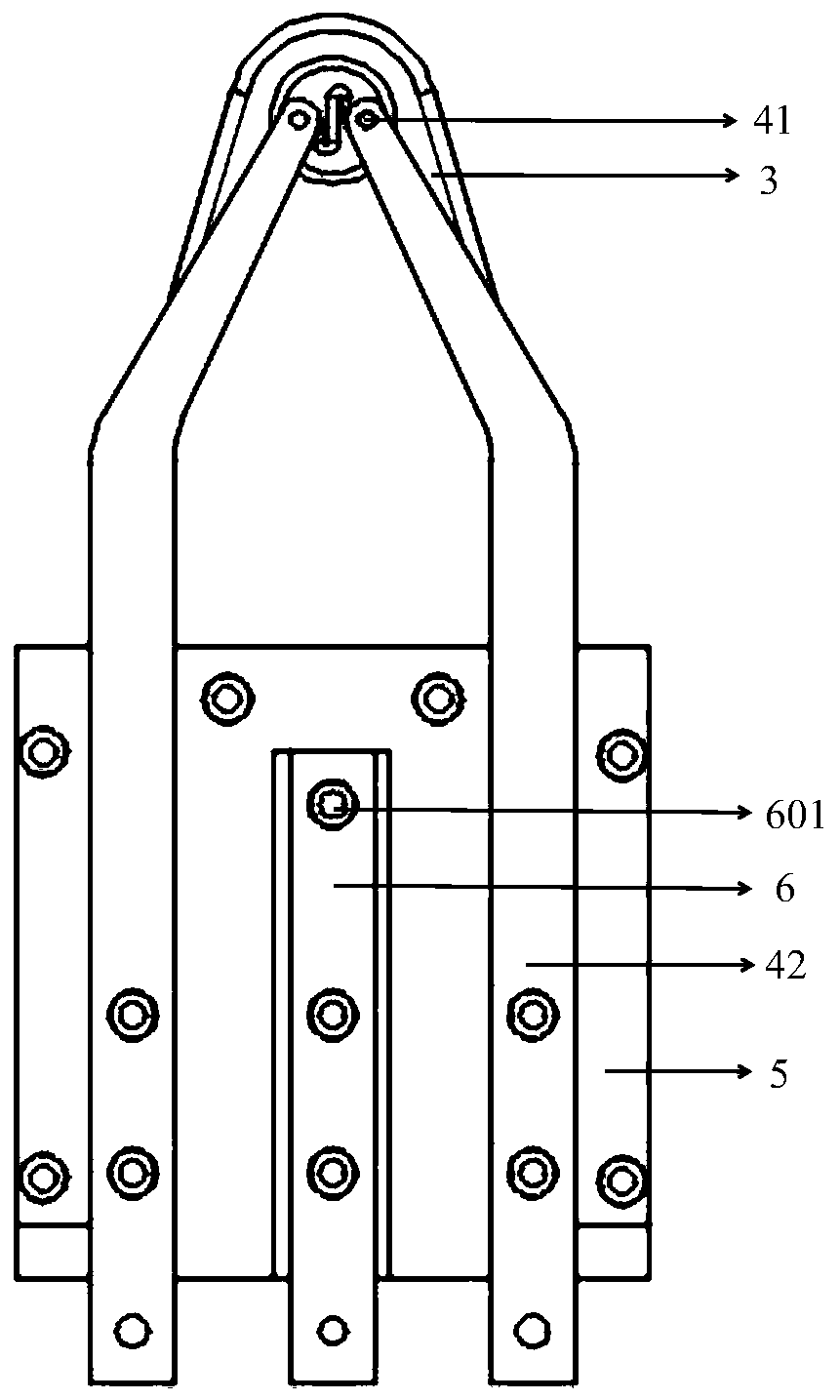
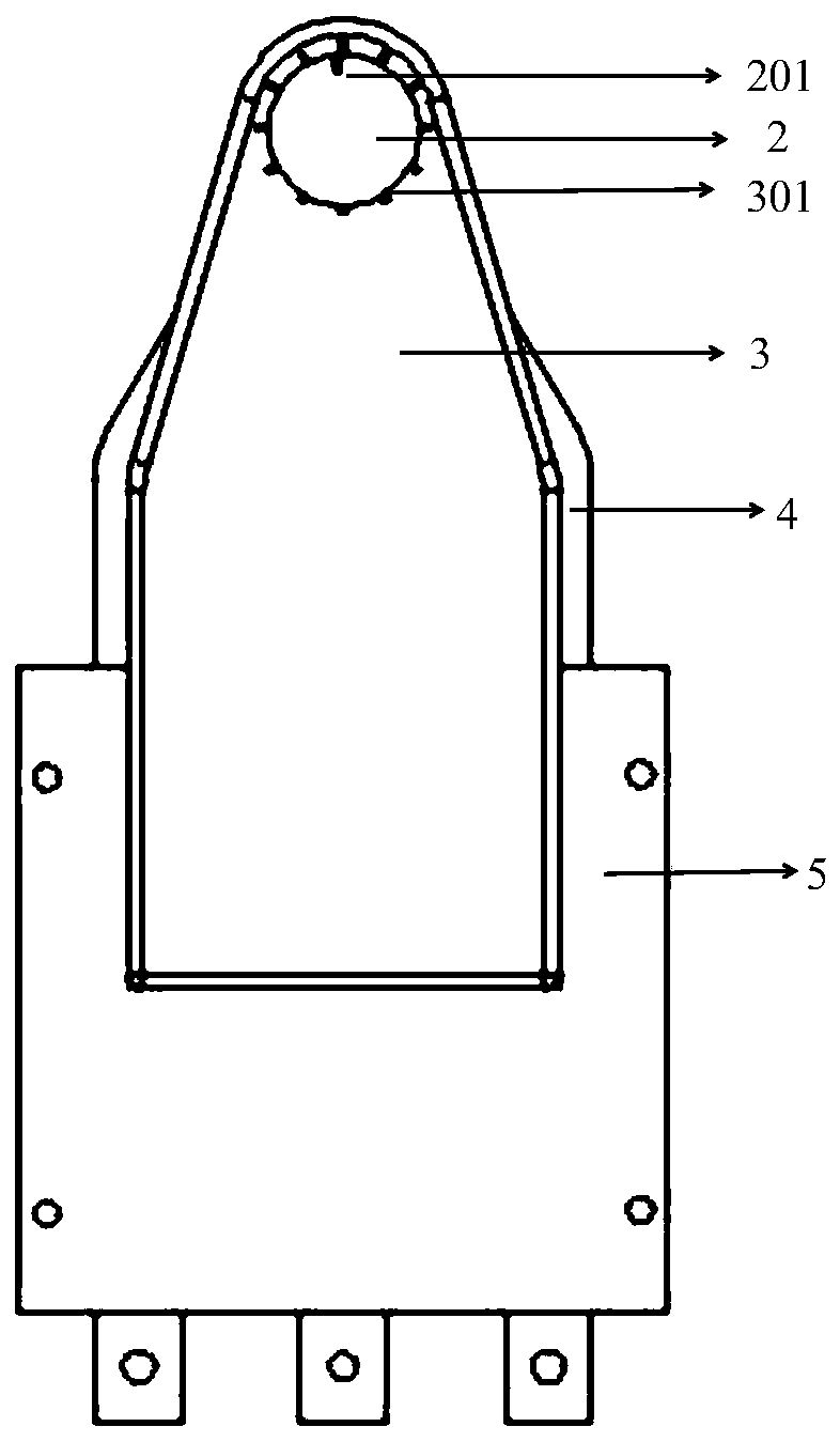
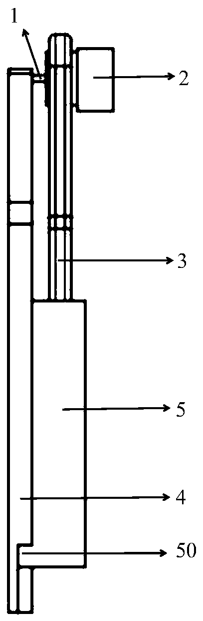
[0035] The present invention includes a mounting device for an ion source, such as Figure 1-7 As shown, ion so...


PUM


Abstract

The invention relates to the technical field of semiconductor processing equipment, in particular to an installation device of an ion source. The ion source comprises a cathode electrode arranged on the opening side of an arcing chamber. One end of the cathode electrode is provided with an opening. The filament is located in the opening and keeps a certain distance from the cathode electrode. Thecathode electrode protrudes inward from the opening side of the arcing chamber. The installation device comprises a cathode clamp which is used for fixing the cathode electrode; two filament clamps which are respectively used for fixing the two ends of the filament outside the arc starting room so as to keep the distance between the filament and the cathode electrode; and an insulating disk of which the front surface is provided with a first positioning structure, wherein one end of the cathode clamp is fixed on the first positioning structure, the back surface of the insulating disk is provided with a second positioning structure and one end of each of the two filament clamps is fixed on the second positioning structure. The beneficial effects are as follows: the installation time of thefilament is reduced and the filament offset caused by screw loosening or heating deformation can be prevented; and the position of the cathode electrode and the filament can be conveniently adjusted so as to ensure their spacing.

Description

technical field [0001] The invention relates to the technical field of semiconductor processing equipment, in particular to an ion source installation device. Background technique [0002] The working principle of the ion source device is: the filament is located on the outside of the cathode electrode and keeps a certain distance from each other to achieve electrical isolation. The cathode electrode protrudes from the opening on the side of the arc chamber to the inside for electrical isolation. , the thermal electrons emitted by the filament hit the cathode electrode continuously and convert the energy to the cathode electrode, so that the temperature of the cathode electrode is increased to achieve the effect of heating the cathode electrode. When the cathode electrode is heated to a certain temperature, a high voltage is provided to the arc starting chamber arc power supply. The high-temperature cathode electrode emits high-energy free electrons into the space in the ar...

Claims


Application Information

Patent Timeline
Patent Type & Authority Applications(China)
IPC IPC(8): H01J9/18H01J3/04H01J27/08
CPCH01J9/18H01J3/04H01J27/08H01J2203/04
Inventor 周华佗
Owner WUHAN XINXIN SEMICON MFG CO LTD
Why Eureka
Try Eureka