Array lens, lens antenna and electronic equipment

A technology of array lens and lens antenna, applied in the direction of antenna, antenna array, specific array feeding system, etc., can solve the problems of limited scanning angle, limited scanning angle of lens antenna, unfavorable coverage, etc.

Active Publication Date: 2020-01-24
GUANGDONG OPPO MOBILE TELECOMM CORP LTD
View PDF38 Cites 1 Cited by
  • Summary
  • Abstract
  • Description
  • Claims
  • Application Information

AI Technical Summary

Problems solved by technology

The electromagnetic waves radiated by a general lens antenna at a feed source that is far away from the lens focus cannot be well converged, so that the scanning angle of the lens antenna is limited. The scanning angle is limited, which is not conducive to covering a large area.

Method used


Image

  • Array lens, lens antenna and electronic equipment
  • Array lens, lens antenna and electronic equipment
  • Array lens, lens antenna and electronic equipment

Examples


Embodiment Construction

[0026] In order to make the purpose, technical solutions, and advantages of this application clearer, the following further describes this application in detail with reference to the accompanying drawings and embodiments. It should be understood that the specific embodiments described here are only used to explain the application, but not to limit the application.

[0027] It can be understood that the terms "first", "second", etc. used in this application can be used herein to describe various elements, but these elements are not limited by these terms. These terms are only used to distinguish the first element from another element, and cannot be understood as indicating or implying relative importance or implicitly indicating the number of indicated technical features. Therefore, the features defined with "first" and "second" may explicitly or implicitly include at least one of the features. In the description of the present application, "a plurality of" means at least two, su...


PUM

PropertyMeasurementUnit
angleaaaaaaaaaa

Abstract

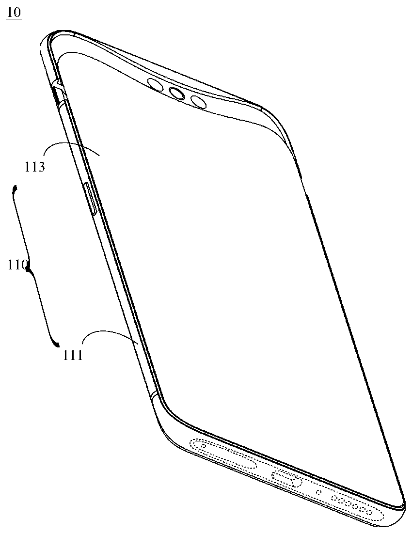
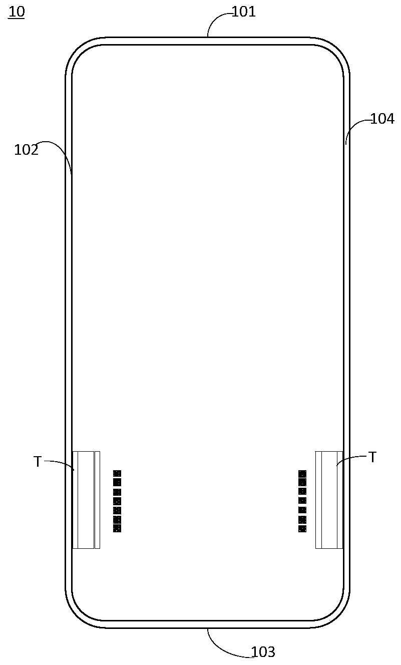
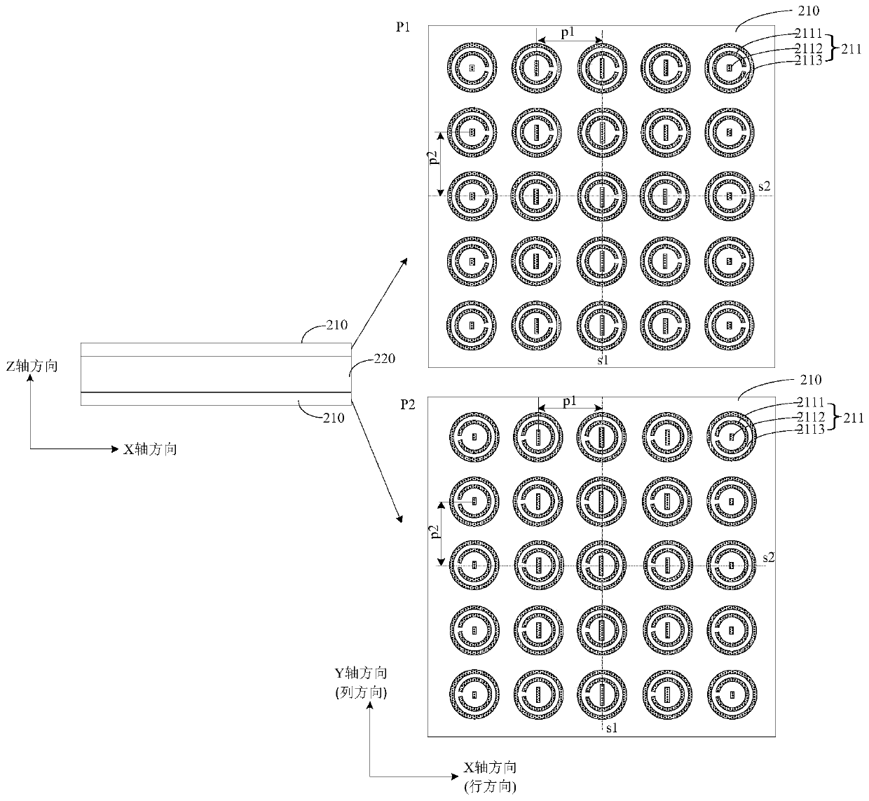
The invention relates to an array lens, a lens antenna and electronic equipment. The array lens comprises a dielectric layer and two layers of array structures respectively arranged on two opposite sides of the dielectric layer. The array structures are provided with a plurality of gap units which are arranged in a two-dimensional array. Each gap unit comprises a closed ring gap, an open ring gapand a strip-shaped gap which are separated from one another, the closed ring gap is arranged around the open ring gap, and the open ring gap is arranged around the strip-shaped gap. Every two gap units, located at the same opposite position, in the two layers of array structures are coaxially arranged, and the opening directions of the open ring gaps in the two gap units are opposite. The strip-shaped gaps in the gap units of the same array structure have gradually changed gap sizes in the array direction. Phase distribution of different frequency bands can be compensated, so that electromagnetic waves radiated by a feed source far away from a focus can be well gathered, the decrease amplitude of off-focus beam gain is greatly reduced, and the scanning angle of the lens antenna is greatlyincreased.

Description

Technical field [0001] This application relates to the field of antenna technology, in particular to an array lens, a lens antenna and an electronic device. Background technique [0002] Lens antenna is an antenna that can convert spherical or cylindrical waves from point sources or line sources into plane waves through electromagnetic waves to obtain pen-shaped, fan-shaped or other beams. By appropriately designing the lens surface shape and refractive index, the phase velocity of the electromagnetic wave is adjusted to obtain the plane wavefront on the radiation aperture. The electromagnetic waves radiated by the general lens antenna from the feed source far away from the lens focus cannot be better converged, so that the scanning angle of the lens antenna is limited, and the scanning angle is limited, which is not conducive to covering a large area. Summary of the invention [0003] The embodiments of the present application provide an array lens, a lens antenna, and an electr...

Claims


Application Information

Patent Timeline
Patent Type & Authority Applications(China)
IPC IPC(8): H01Q15/02H01Q19/06H01Q1/50H01Q21/00H01Q1/22
CPCH01Q1/22H01Q1/50H01Q15/02H01Q19/06H01Q21/0006
Inventor 杨帆
Owner GUANGDONG OPPO MOBILE TELECOMM CORP LTD
Why Eureka
Try Eureka