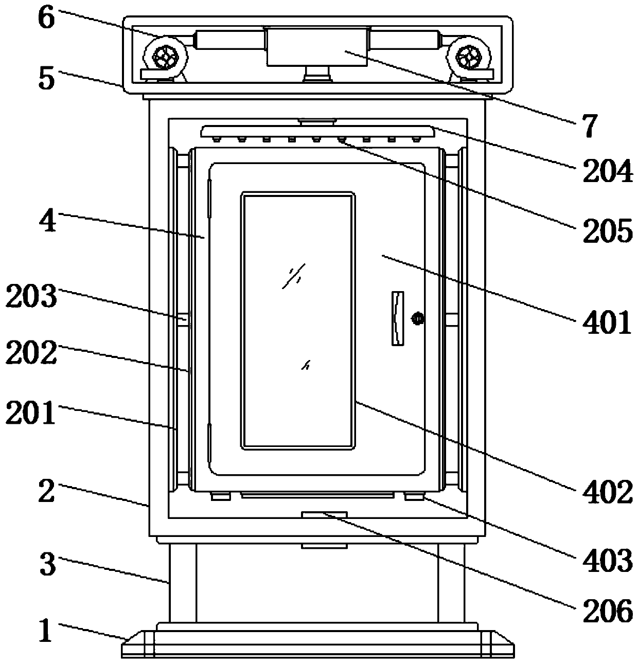
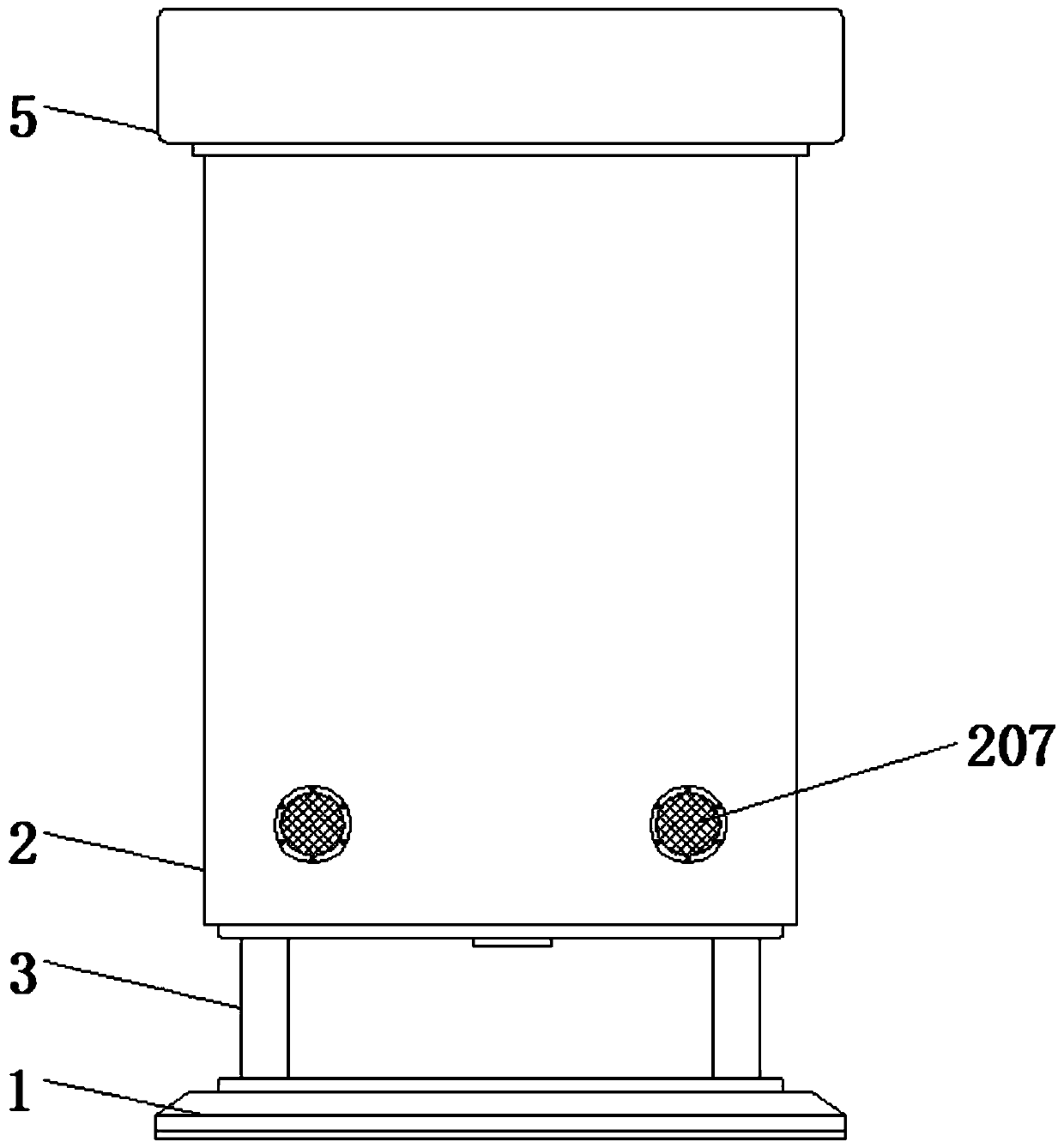
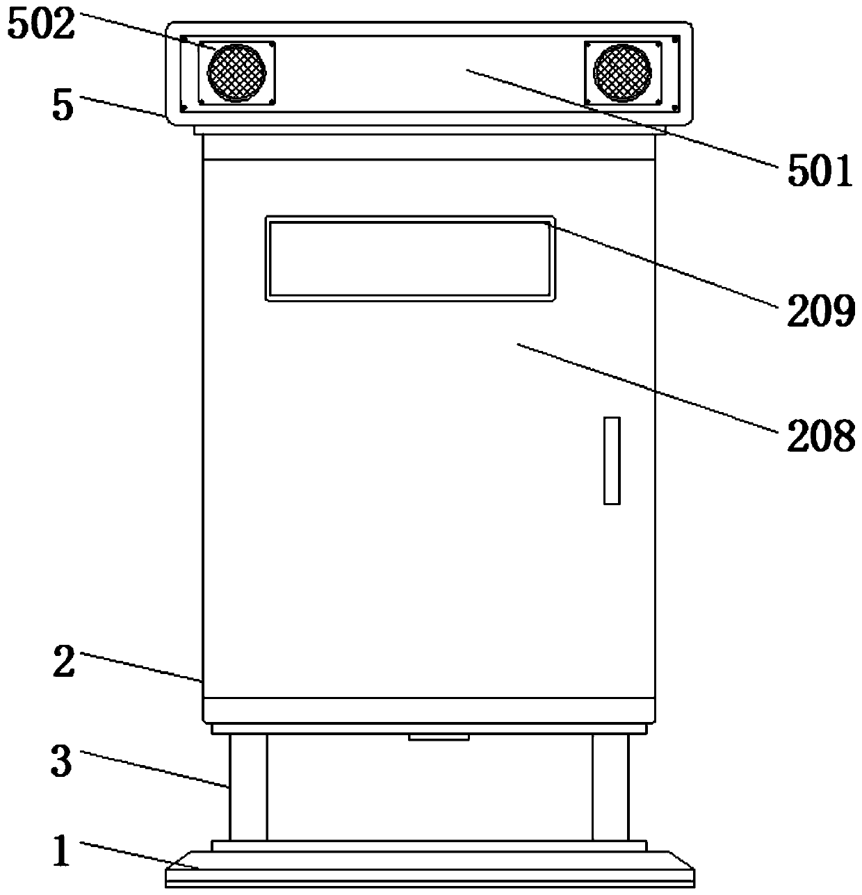
Refrigerating unit electric appliance control box with built-in protection structure

A technology for electrical control boxes and refrigerating units, which is applied in the direction of casing/cabinet/drawer parts, electrical components, electrical equipment structural parts, etc. Problems such as deformation and damage can be achieved to increase the effect of ventilation and heat dissipation, avoid circuit breakage, and facilitate inspection and maintenance.

Inactive Publication Date: 2020-01-24
XUZHOU SANHE AUTOMATIC CONTROL EQUIP
View PDF6 Cites 4 Cited by
  • Summary
  • Abstract
  • Description
  • Claims
  • Application Information

AI Technical Summary

Problems solved by technology

[0004] Although the existing patent (notification number: CN102548274A) discloses a kind of electrical control box, comprises the first air inlet (1) that is arranged on the first side wall (7), the outlet that is arranged on the second side wall (9) The tuyere (2) also includes at least one splint (5), but in the process of realizing the present invention, the inventor found that at least the following problems in the prior art have not been solved;
[0005] There are still the following defects: 1. The overall protection performance is poor, especially the internal protection part is relatively weak. When the control box is subjected to external collision or man-made damage, it is easy to cause deformation and damage to the control box, and even cause internal device components. The failure situation affects the work progress and shortens the service life; 2. At the same time, the control box cannot be better protected according to the change of outdoor solar energy, which will easily cause the control box to be affected by the change of air temperature and affect the normal operation of the internal electrical components, reducing the Practical performance of the control; 3. And the isolation effect inside the control box is poor. When the electrical components inside the control box fail and cause leakage, it will cause more inconvenience to the staff during maintenance operations, so it is necessary to Improvements were made to address the above issues

Method used


Image

  • Refrigerating unit electric appliance control box with built-in protection structure
  • Refrigerating unit electric appliance control box with built-in protection structure
  • Refrigerating unit electric appliance control box with built-in protection structure

Examples


Embodiment Construction

[0028] The following will clearly and completely describe the technical solutions in the embodiments of the present invention with reference to the accompanying drawings in the embodiments of the present invention. Obviously, the described embodiments are only some, not all, embodiments of the present invention. Based on the embodiments of the present invention, all other embodiments obtained by persons of ordinary skill in the art without making creative efforts belong to the protection scope of the present invention.

[0029] In the description of the present invention, it should be noted that the terms "upper", "lower", "inner", "outer", "front end", "rear end", "both ends", "one end", "another end" The orientation or positional relationship indicated by etc. is based on the orientation or positional relationship shown in the drawings, and is only for the convenience of describing the present invention and simplifying the description, rather than indicating or implying that ...


PUM


Abstract

The invention discloses a refrigerating unit electric appliance control box with a built-in protection structure. The refrigerating unit electric appliance control box comprises an outer shell and aninner shell. A base is fixedly mounted at the bottom of the outer shell through supporting rods. A mounting cavity is fixedly mounted at the top of the outer shell. Fans are fixedly mounted on the twosides of the interior of the mounting cavity. A mounting chamber is fixedly mounted at the top end of the interior of the mounting cavity. The output ends of the fans are communicated with the mounting chamber through mounting cylinders, and resistance heating wires are fixedly mounted in the mounting cylinders. Supporting plates, fixing pieces and reinforcing plates improve the overall strengthof the control box, avoid or reduce the deformation of the control box due to collision or manual damage, and better guarantee stable operation of the control box. The inner shell and the outer shellachieve a double-layer protection effect on the control box. Therefore, stable operation of the control box is guaranteed, the influence of external things on the control box is reduced, and the service life of the control box is prolonged.

Description

technical field [0001] The invention relates to the technical field of control boxes, in particular to an electrical control box of a refrigeration unit with a built-in protective structure. Background technique [0002] The composition of the refrigeration unit: compressor (compressor-like subsystem), condenser, expansion valve, evaporator and control system, etc. The refrigeration compressor is the most important equipment in the refrigeration unit, usually called the host in the refrigeration unit, the refrigerant The increase of vapor from low pressure to high pressure and the continuous flow and transportation of vapor are all completed by the work of refrigeration compressors. When the refrigeration unit is in operation, because there are many electrical components, it needs to be controlled by the corresponding electrical control box. The electrical appliances on the refrigeration unit perform unified control operations. [0003] The control box is suitable for openi...

Claims


Application Information

Patent Timeline
Patent Type & Authority Applications(China)
IPC IPC(8): H05K5/02H05K7/20
CPCH05K5/0217H05K7/20H05K7/20136
Inventor 董悦串
Owner XUZHOU SANHE AUTOMATIC CONTROL EQUIP
Why Eureka
Try Eureka