Tin ball separating device

A separation device and technology of solder balls, applied in the directions of transportation and packaging, conveyor objects, etc., can solve the problems of low separation efficiency of solder balls, easy occurrence of ball jamming, etc., achieve fast and efficient separation and feeding, avoid jamming, improve The effect of separation efficiency

Pending Publication Date: 2020-01-31
东莞道元自动化技术有限公司
View PDF0 Cites 3 Cited by
  • Summary
  • Abstract
  • Description
  • Claims
  • Application Information

AI Technical Summary

Problems solved by technology

[0003] The purpose of the present invention is to provide a solder ball separation device, which aims to solve the problem that the solder ball separation device in the prior art is prone to jamming, resulting in low solder ball separation efficiency

Method used


Image

  • Tin ball separating device
  • Tin ball separating device
  • Tin ball separating device

Examples


Embodiment Construction

[0025] In order to make the technical problems, technical solutions and beneficial effects to be solved by the present invention clearer, the present invention will be further described in detail below in conjunction with the accompanying drawings and embodiments. It should be understood that the specific embodiments described here are only used to explain the present invention, not to limit the present invention.

[0026] It should be noted that when an element is referred to as being “connected to” or “disposed on” another element, it may be directly on the other element or be indirectly on the other element. When an element is referred to as being "connected to" another element, it can be directly connected to the other element or indirectly connected to the other element.

[0027] In addition, the terms "first" and "second" are used for descriptive purposes only, and cannot be interpreted as indicating or implying relative importance or implicitly specifying the quantity o...


PUM


Abstract

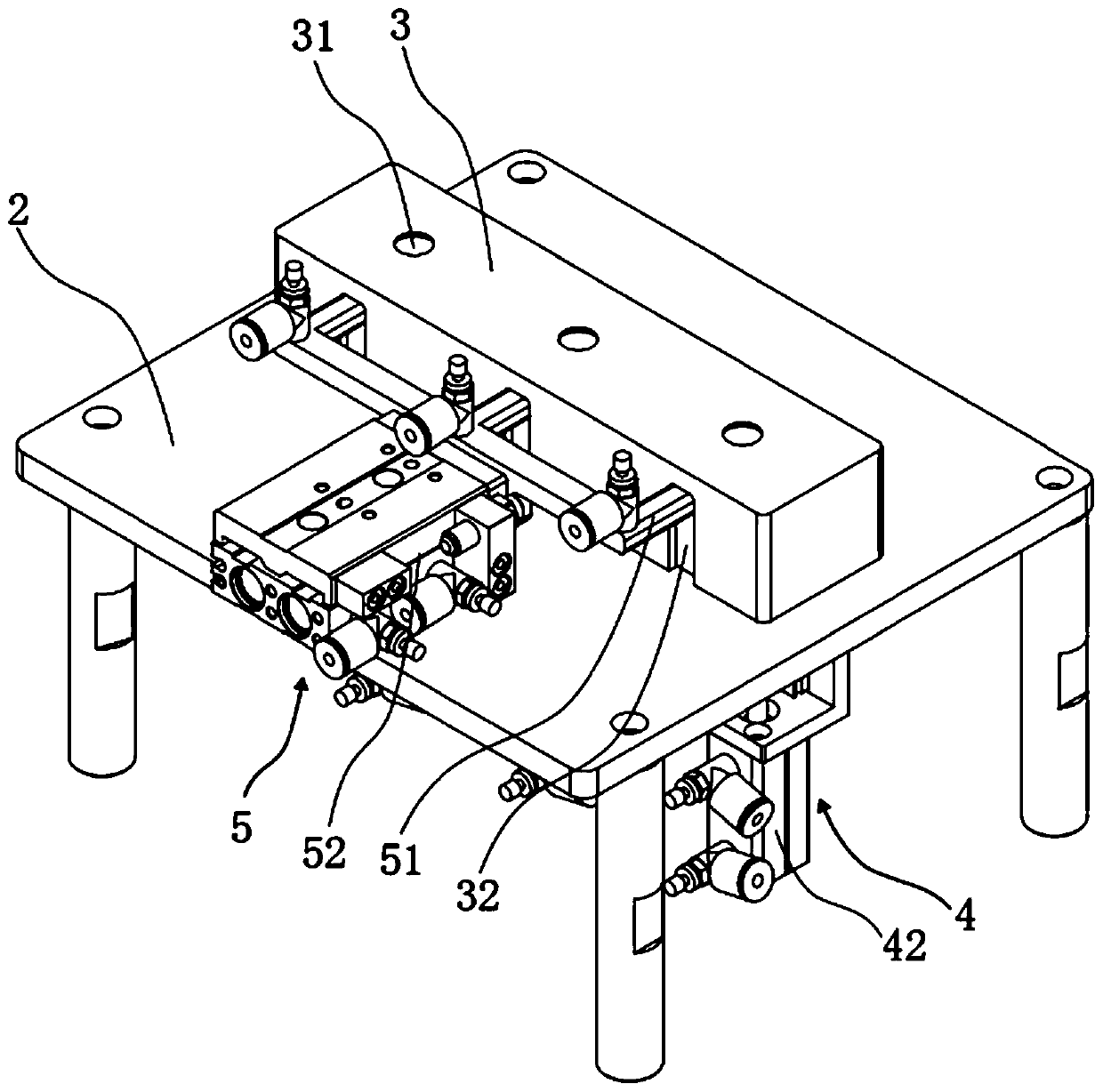
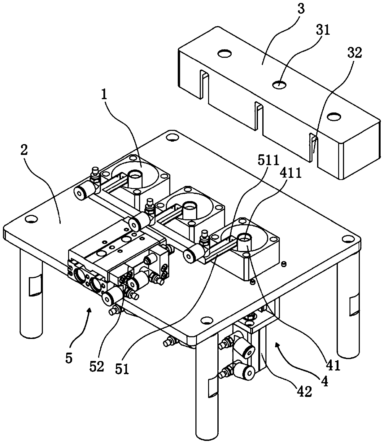
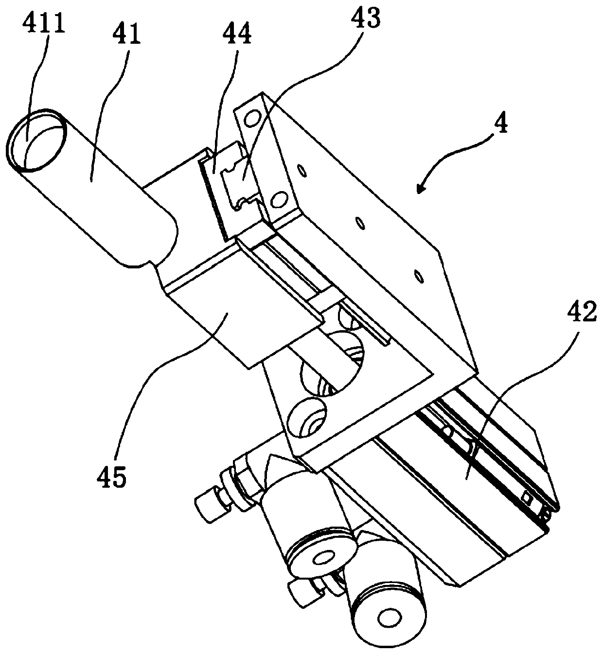
The invention provides a tin ball separating device. The tin ball separating device comprises a material hopper used for storing tin balls, a machine table for supporting the material hopper, a shieldbody used for shielding the material hopper and a material moving mechanism used for moving tin balls in the material hopper; the material hopper is located in the shield body; a material fetching opening through which a sucking head of a manipulator extends into the shield body; the material moving mechanism comprises a material moving post arranged in the material hopper and a first linear driving mechanism which drives the material moving post to move the tin balls to the material fetching opening to be sucked by the sucking head; the first linear driving mechanism is arranged on the machine table; and the material moving post is connected to the first linear driving mechanism. During use, the first linear driving mechanism drives the material moving post to move the tin balls in the material hopper to the material fetching opening in the shield body, so that the tin balls in the material hopper can be separated rapidly, high-efficiently and automatically; a ball blocking phenomenon cannot occur; the tin ball separation efficiency is high; the tin ball separating device can also be applied to separation of tin balls of different sizes; and the situation that various tin ball separation devices need to be arranged for tin balls of different sizes can be avoided.

Description

technical field [0001] The invention belongs to the technical field of solder ball welding, and more specifically relates to a solder ball separating device. Background technique [0002] With the development of science and technology, precision components such as electronic products are becoming more and more miniaturized, the manufacturing process is becoming more and more complex, and the welding conditions are becoming more and more harsh. Solder ball welding technology is widely used in cutting-edge packaging technology and micro-welding occasions. At present, the structure of the solder ball separation device of the solder ball soldering equipment is complicated, and the solder balls generally have strong viscosity, and ball jamming is easy to occur when the solder balls are separated, resulting in low separation efficiency of the solder balls and affecting the welding efficiency of the solder ball soldering. Contents of the invention [0003] The object of the prese...

Claims


Application Information

Patent Timeline
Patent Type & Authority Applications(China)
IPC IPC(8): B65G47/91
CPCB65G47/912
Inventor 王全林张光展
Owner 东莞道元自动化技术有限公司
Why Eureka
Try Eureka