Self-adaptive defrosting control method of air-cooled heat pump system

An air-cooled heat pump and control method technology, which is applied in defrosting, application, refrigerator and other directions, can solve the problems of no defrosting without frost, no defrosting with frost thickness, and reduction in condensation temperature, and achieve stable and smooth operation of defrosting control. , The defrosting control operation is more, and the effect of reliable operation is guaranteed.

Inactive Publication Date: 2020-01-31
WUXI VOCATIONAL & TECHN COLLEGE
View PDF4 Cites 3 Cited by
  • Summary
  • Abstract
  • Description
  • Claims
  • Application Information

AI Technical Summary

Problems solved by technology

Since the temperature is considered on the basis of the time, it is an improvement over the simple time method, and partly considers the influence of the outdoor working environment of the air conditioner, but it still cannot correctly reflect the impact of frost on the performance of the air conditioner, and unnecessary defrosting operation, and will not send a defrosting signal when defrosting is required
[0009] (3) The defrosting control method of the difference between the evaporation temperature and the atmospheric temperature: when the frost on the surface of the evaporator is serious, the difference between the evaporation temperature and the atmospheric temperature will increase, and the defrosting control according to this change reflects the working characteristics of the air conditioner after frosting The influence produced, but judging only based on the change of a quantity will also cause misoperation
[0010] (4) When frosting on the surface of the evaporator is serious, the condensation temperature will decrease. Controlling defrosting according to the change of

Method used


Image

  • Self-adaptive defrosting control method of air-cooled heat pump system
  • Self-adaptive defrosting control method of air-cooled heat pump system
  • Self-adaptive defrosting control method of air-cooled heat pump system

Examples


Embodiment 1

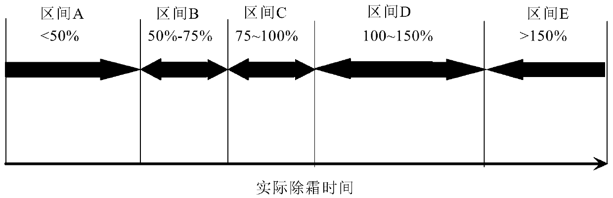
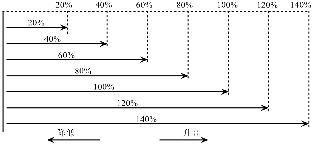
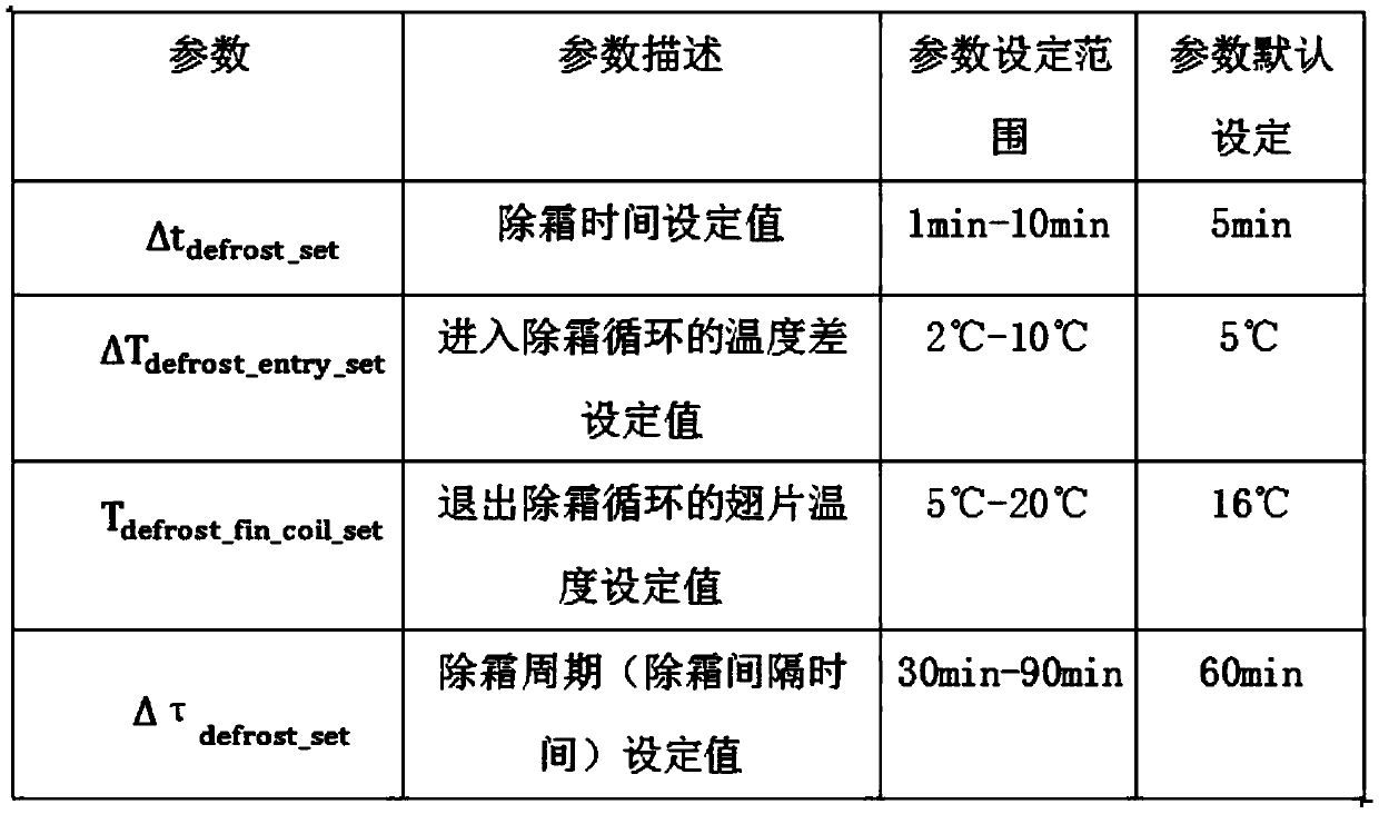
[0026] Embodiment 1: as figure 1 and figure 2 As shown, an adaptive defrosting control method for an air-cooled heat pump system, based on the dynamic change characteristics of each parameter of the air-cooled heat pump, an adaptive optimal defrosting control method, this control method requires four control parameters: (1 )Defrosting time setting value Δt defrost_set , (2) The set value ΔT of the temperature difference entering the defrosting cycle defrost_entr_set , (3) The set value T of the fin temperature exiting the defrosting cycle defrost_fin_coil_set , (4) The set value Δτ of the interval time between two defrosting cycles (defrosting cycle) defrost_set .

[0027] Δt defrost_set : The set value of the defrosting time refers to the defrosting time between entering the defrosting cycle and exiting the defrosting cycle;

[0028] ΔT defrost_entry_set =T frost_Air -T frost_coil_fin : The set value of the temperature difference entering the defrosting cycle refers...


PUM


Abstract

The invention discloses a self-adaptive defrosting control method of an air-cooled heat pump system. The self-adaptive defrosting control method is characterized by comprising the following steps of:setting four control parameters: (1) setting a defrosting time set value; (2) setting a temperature difference value entering a defrosting cycle; (3) setting a fin temperature exiting the defrosting cycle; and (4) setting an interval time (defrosting cycle) of two defrosting cycles, comparing actual defrosting time with set defrosting time, recording a ratio of the actual defrosting time to the set defrosting time each time, setting an interval according to a ratio range, determining a defrosting interval time according to an interval range to which the defrosting interval time belongs, takingtwo times of defrosting time as a correction interval, adjusting the set value of the defrosting interval time according to two defrosting time intervals recorded by the current times and the previous times, and continuously correcting the defrosting cycle to enable the defrosting cycle to automatically adapt to the change of the temperature and humidity of the environment with a self-correctionvariable step length.

Description

technical field [0001] The invention relates to the technical field of defrosting control methods, in particular to an adaptive defrosting control method for an air-cooled heat pump system. Background technique [0002] When the system is cooling or heating, frosting may occur. If defrosting is not timely after frosting, it will affect the use of the refrigeration system or heating system. [0003] Refrigeration and frosting are generally located on the evaporator of the indoor unit. When cooling, the outdoor unit dissipates heat and the indoor unit absorbs heat. The purpose of the evaporator is to absorb heat (cool down), and absorbing heat requires air circulation, which is carried away by air conduction. Heat, when the air flow is insufficient, the evaporator will frost, and the reason for insufficient air is often that the filter screen is not cleaned or the cooling fins of the evaporator are not cleaned, which hinders the air flow. [0004] Heating frost is usually loc...

Claims


Application Information

Patent Timeline
IPC IPC(8): F25B49/02F25D21/00
CPCF25B49/02F25D21/002
Inventor 商萍君朱倩陈利军陈武王明星
Owner WUXI VOCATIONAL & TECHN COLLEGE
Why Eureka
Try Eureka