Starting impact current suppression circuit

A technology to start the inrush current and start the circuit, which is applied in the direction of high-efficiency power electronic conversion, electrical components, and adjustment of electrical variables, etc., can solve problems such as abnormal operation, affect circuit complexity, and voltage drop, and achieve the effect of ensuring reliable operation

Pending Publication Date: 2022-04-12
SHANGHAI JARI INFORAMTION SCI & TECH
View PDF0 Cites 0 Cited by
  • Summary
  • Abstract
  • Description
  • Claims
  • Application Information

AI Technical Summary

Problems solved by technology

[0003] 1. The components of the power input part (such as power switches, fuses, rectifiers, etc.) will be damaged by a large electrical stress, which increases the failure rate of these components and leads to a significant decrease in the mean time between failures (MTBF) of the whole machine
[0004] 2. Generate additional electromagnetic interference, which interferes with other nearby electronic equipment in the form of conduction and radiation, which may cause it to malfunction instantly
[

Method used


Image

  • Starting impact current suppression circuit
  • Starting impact current suppression circuit
  • Starting impact current suppression circuit

Examples


Embodiment Construction

[0023] In order to make the purpose, technical solution and advantages of the present application clearer, the present application will be further described in detail below in conjunction with the accompanying drawings and embodiments. It should be understood that the specific embodiments described here are only used to explain the present application, and are not intended to limit the present application.

[0024] It should be noted that if there are descriptions involving "first", "second", etc. in the embodiments of the present invention, the descriptions of "first", "second", etc. are only for description purposes, and should not be interpreted as instructions or Implying their relative importance or implying the number of technical features indicated. Thus, the features defined as "first" and "second" may explicitly or implicitly include at least one of these features. In addition, the technical solutions of the various embodiments can be combined with each other, but it...


PUM

PropertyMeasurementUnit
Second resistoraaaaaaaaaa
Third resistoraaaaaaaaaa
Fifth resistoraaaaaaaaaa

Abstract

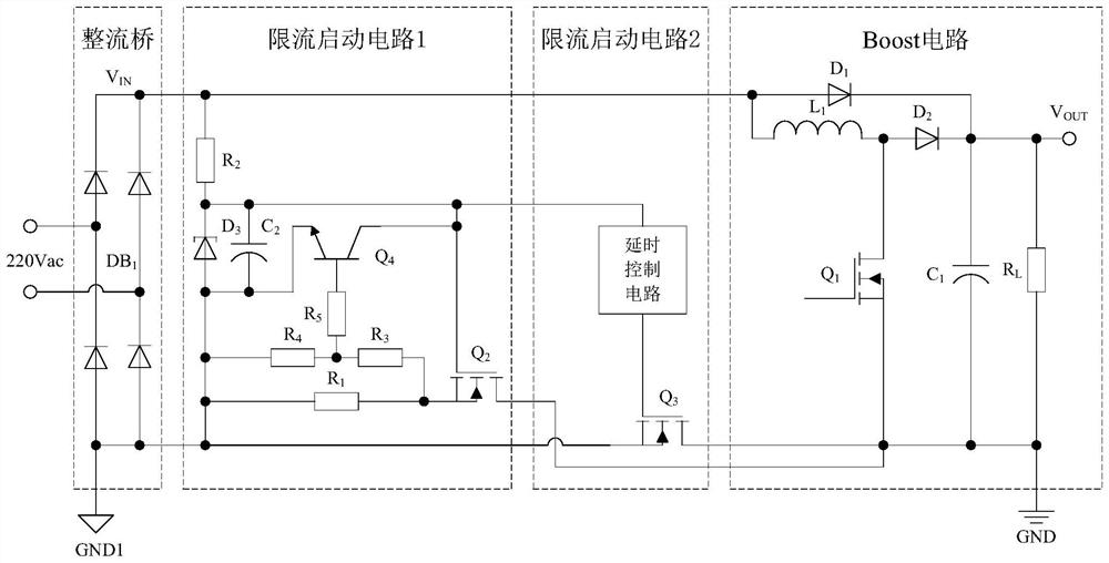
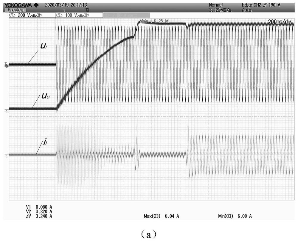
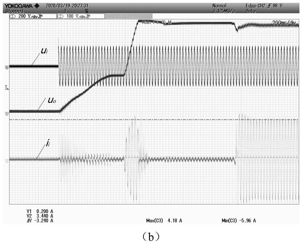
The invention discloses a starting impact current suppression circuit which comprises a rectifier bridge, a first current-limiting starting circuit, a second current-limiting starting circuit and a Boost circuit. The input end of the rectifier bridge is connected with an alternating current power supply, the output positive end of the rectifier bridge is connected with the input positive end of the first current-limiting starting circuit and the input positive end of the Boost circuit, and the output negative end of the rectifier bridge is connected with the input negative end of the first current-limiting starting circuit and the MOSFET source electrode of the second current-limiting starting circuit; the first output end of the first current-limiting starting circuit is connected with the input end of the second current-limiting starting circuit, and the second output end of the first current-limiting starting circuit is connected with the output negative end of the Boost circuit; the output negative end of the Boost circuit is connected with the drain electrode of the MOSFET of the second current-limiting starting circuit, and the output positive end of the Boost circuit is VOUT. According to the invention, the starting impact current in the power factor correction circuit can be effectively suppressed, the current is limited within 4A, and the reliable operation of the circuit is ensured.

Description

technical field [0001] The invention belongs to the technical field of electronics and electrics, in particular to a starting surge current suppression circuit applied to electronic equipment such as active power factor correction (APFC). Background technique [0002] In order to improve the quality of switching power supply and electromagnetic compatibility of electronic equipment, built-in APFC circuit is generally used to eliminate current harmonics and improve power factor, while the main power circuit of traditional APFC circuit is completed by Boost step-up circuit. It is converted into a DC voltage and input to the Boost circuit, and the Boost circuit boosts the voltage to an output of about 380V. Usually, a large number of filter capacitors (energy storage capacitors in the Boost circuit) are added to the output of the APFC circuit to reduce the output ripple of the subsequent DC / DC converter, so the capacitor must absorb a large amount of current at the moment of po...

Claims


Application Information

Patent Timeline
IPC IPC(8): H02M1/32H02M1/36H02M1/42H02M7/06H02M3/156
CPCY02B70/10
Inventor 宋旭东曹志东杨帆汤晖斌郝英杰阳良春朱刘英王凯肖化
Owner SHANGHAI JARI INFORAMTION SCI & TECH
Why Eureka
Try Eureka