Blasting vibration measurement method for excavating plant

A blasting vibration and open-air technology, which is applied in measuring devices, radio wave measuring systems, and measuring ultrasonic/sonic/infrasonic waves, etc., can solve problems such as difficult alignment of blasting centers, difficult alignment, and poor accuracy of blasting vibration measurement points, etc. problem, to achieve the effect of improving accuracy, overcoming inaccurate position, and accurate positioning

Active Publication Date: 2020-01-31
CHINA MINMETALS CHANGSHA MINING RES INST
View PDF6 Cites 1 Cited by
  • Summary
  • Abstract
  • Description
  • Claims
  • Application Information

AI Technical Summary

Problems solved by technology

[0005] (1) The accuracy of the selected points for blasting vibration measurement is too poor
The currently carried out blasting vibration measurement work basically determines the measurement points on the spot based on experience, and it cannot guarantee that the selected measurement points are all located on a straight line (i.e., the layout line), which affects the reliability of the blasting vibration measurement results.
[0006] (2) The positive direction of the sensor of the blasting vibration monitor is difficult to align with the blasting center
The blasting vibration measurement work on site is greatly affected by the stope slope, stope layout, and stope status quo. The installation personnel cannot see the position of the blasting center at all. Even if they can see it, it is difficult to align the blasting center with the naked eye. It is even more difficult to align the blasting center when they cannot see the blasting center. , making it difficult to guarantee the accuracy of the monitored data

Method used


Image

  • Blasting vibration measurement method for excavating plant

Examples


Embodiment Construction

[0031] The embodiments of the present invention will be described in detail below with reference to the accompanying drawings, but the present invention can be implemented in various ways defined and covered by the claims.

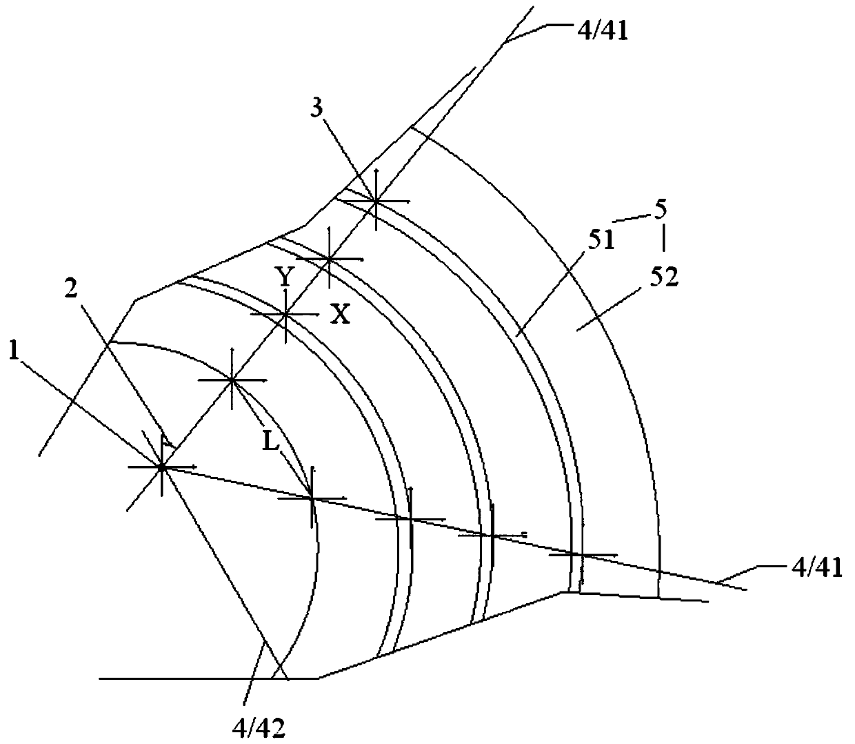
[0032] by figure 1 As an example, an open pit blasting vibration measurement method includes the following steps:

[0033] 1) Determine the position of the blasting center 1 in the central area of ​​the stope. The blasting center is generally designed by the blasting operator according to the production plan and the stope situation. Mark the position of the center; carry out on-site investigation on the slope 5 of the open pit to understand the topography, geology, hydrology and mining conditions of the slope, and record the bedrock distribution on the slope; based on the location of the blasting center and the bedrock According to the distribution situation, the line in the open-pit stope with many bedrock masses and located close to the slope platform 5...


PUM


Abstract

The invention provides a blasting vibration measurement method for an excavating plant, wherein the method is specially set for the slope terrain of an excavating plant. An accurate orientation of anarrangement line and accurate coordinates of a measuring point are determined by combining the topographic and geomorphic investigation situation of a site and a current topographic map; a GPS measuring instrument is used for finding out the coordinates of the measuring point at a site; after finding of the coordinates of the measuring point, a bed rock body for installing a sensor is selected, and X, Y and Z coordinates of the position of the bed rock body for installing a sensor are recorded and stored for follow-up calculation; and then the sensor is installed by using a geological compassfor assistance. According to the invention, all sensors arranged at the one same arrangement line do not deviate from the arrangement line and the arrow of the sensor is aligned with the blasting center in the forward direction, so that a problem of position inaccuracy caused by manual naked eye observation is solved and the accuracy of blasting vibration monitoring data is improved substantially;the no any influence is caused even when the visual light of the measurement staff is blocked, so that accurate positioning is realized and operation becomes convenient.

Description

technical field [0001] The invention relates to the technical field of mine mining construction monitoring, in particular to a method for measuring blasting vibration in an open-pit stope. Background technique [0002] Due to the generally good ore conditions and hard rock in open-pit metal mining, it is difficult to excavate by ordinary methods. It is necessary to blast the ore before excavation, and then load it out of the stope. Due to the use of blasting to mine ore, it will cause vibration cumulative damage to the slope of the open-pit stope. Under the action of blasting vibration for a long time, internal cracks in the slope develop and penetrate, which eventually leads to the collapse of the stope slope and affects the safe production of the mine. In order to avoid the impact of the blasting operation on the adjacent stope slope (that is, the step slope around the blasting center), it is necessary to measure the blasting vibration of the stope and analyze the impact o...

Claims


Application Information

Patent Timeline
Patent Type & Authority Applications(China)
IPC IPC(8): G01H17/00G01S19/14
CPCG01H17/00G01S19/14
Inventor 王飞飞邹平虎万杰马增李爱兵孟中华刘正宇
Owner CHINA MINMETALS CHANGSHA MINING RES INST
Why Eureka
Try Eureka