Eureka AIR delivers breakthrough ideas for toughest innovation challenges, trusted by R&D personnel around the world.

Intelligent electro-hydraulic lifting control device and intelligent electro-hydraulic lifting control method for paddy field agricultural machine

A control device and electro-hydraulic technology, which is applied to the hoisting device of agricultural machinery, agricultural machinery, and adjustment device, etc., can solve the problems of increasing labor intensity, affecting work efficiency, and difficult to control the slip rate, so as to achieve enhanced fuel economy, The device has a compact structure and the effect of reducing labor intensity

Pending Publication Date: 2020-02-04
ZOOMLION HEAVY MASCH CO LTD
View PDF11 Cites 3 Cited by
  • Summary
  • Abstract
  • Description
  • Claims
  • Application Information

AI Technical Summary

Problems solved by technology

[0003] The first point: tractors operate in a straight line in paddy fields, and the slip rate is difficult to control so that traction efficiency and fuel economy control cannot be achieved;
[0004] The second point: tractor paddy field operation until the field head turns around, it is necessary to manually control the lifting and lowering of agricultural machinery, such repeated operations seriously affect work efficiency and increase labor intensity;
[0005] The third point: tractor paddy field operation, the left and right inclination angle of agricultural machinery depends entirely on the vehicle body, and it is impossible to achieve leveling control on agricultural machinery alone, so that it is difficult to achieve the purpose of leveling paddy fields
[0006] The existing patent No. 201710004337.3 is an adaptive lifting device and control method for tractor electro-hydraulic suspension field heads. The technical point of this patent is to judge the U-turn steering by the wheel speed difference of the angle sensor 103 and the wheel speed sensors 106 and 107. The start and end times are judged by the angle sensor and the wheel speed difference between the wheel speed sensors on both sides to determine the start and end of the U-turn. This patent requires the use of two wheel speed sensors, which has problems of complex structure and calculation

Method used


Image

  • Intelligent electro-hydraulic lifting control device and intelligent electro-hydraulic lifting control method for paddy field agricultural machine
  • Intelligent electro-hydraulic lifting control device and intelligent electro-hydraulic lifting control method for paddy field agricultural machine
  • Intelligent electro-hydraulic lifting control device and intelligent electro-hydraulic lifting control method for paddy field agricultural machine

Examples


Embodiment 1

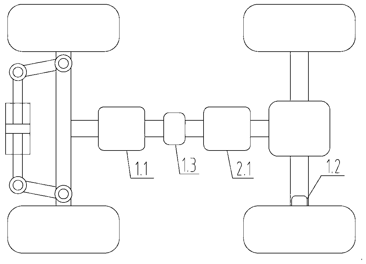
[0062] The slip rate of the agricultural machinery is controlled by the automatic driving controller 1.1 and the wheel speed sensor 1.2.

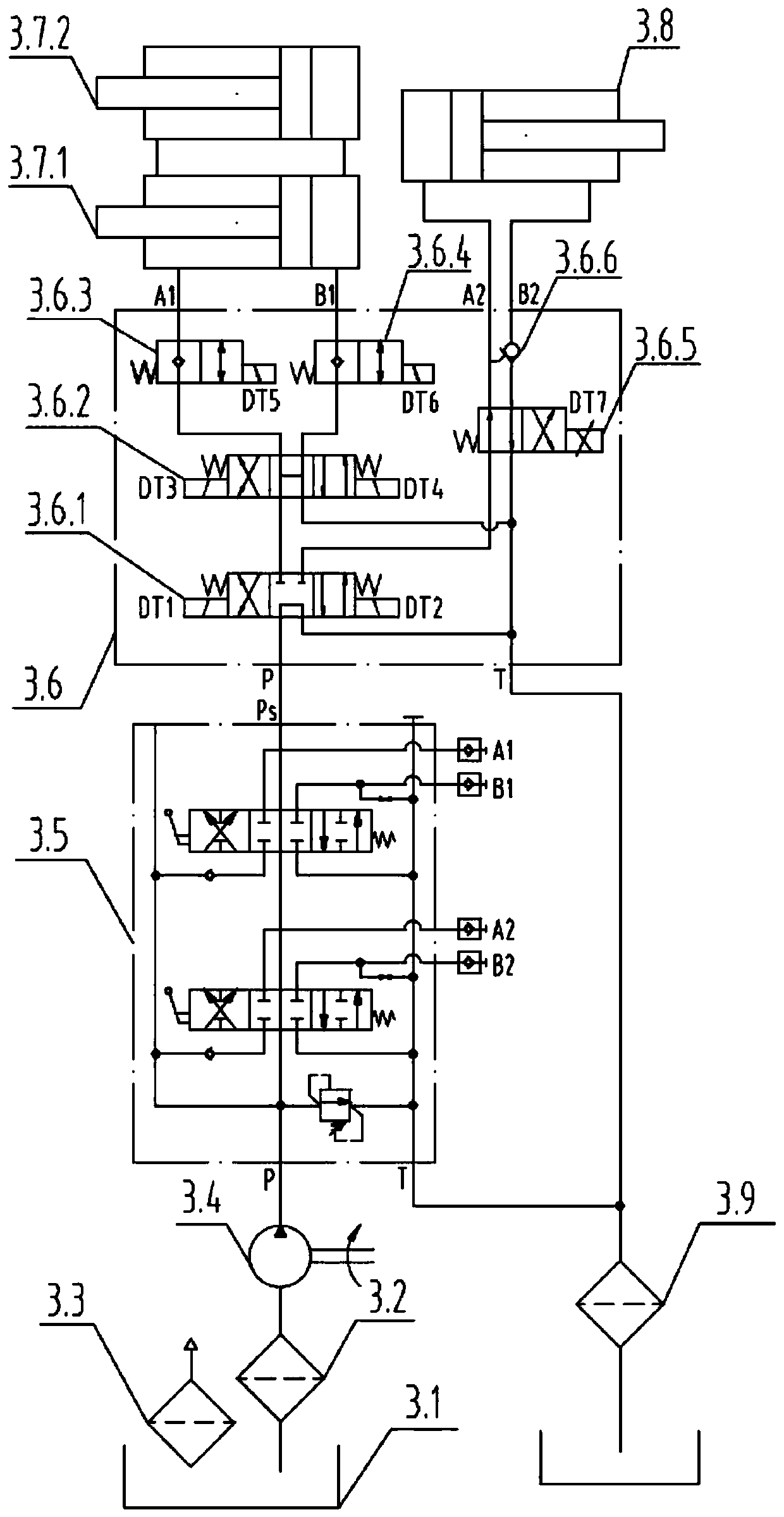
[0063] When the slip rate Sr is greater than 9%, lift the agricultural implements to reduce the plowing depth, and the direction of the oil circuit is the electro-hydraulic lifting controller 2.1 to control the first three-position four-way solenoid valve 3.6.1 to work in the right position (DT2 is energized), and the second No. 3-position, 4-way solenoid valve 3.6.2 works in the left position (DT3 is powered), No. 1, 2-position, 2-way solenoid valve 3.6.3 works in the right position (DT5 is powered), No. 2, 2-position, 2-way solenoid valve 3.6.4 The right position works (DT6 is energized); the pressure oil of the oil pump 3.4 enters the left lift cylinder 3.7.1 and the right lift cylinder 3.7.2 through the multi-way valve 3.5 middle position, each working position of the electro-hydraulic lift control valve block 3.6 and its B1 port Interc...

Embodiment 2

[0067] Utilize the automatic driving controller 1.1 to control the U-turn of the agricultural machinery.

[0068] In order to enable the tractor to automatically lift the agricultural implements to reduce load resistance when the tractor is working until the end of the field and turn around, and automatically lower the agricultural implements to restore the preset plowing depth to the straight line operation when the turn is completed.

[0069] In this technical solution, the automatic driving controller 1.1 outputs two state signals of turning around and working in a straight line to the electro-hydraulic lifting controller 2.1. When turning around and turning, the electro-hydraulic lifting controller 2.1 lifts the agricultural implement according to the preset lifting height; The electro-hydraulic lifting controller 2.1 lowers the agricultural implements according to the preset tillage depth. The direction of the oil passage is the same as that of Embodiment 1, and will not ...

Embodiment 3

[0073] The vehicle body inclination angle sensor 1.3 and the leveling oil cylinder displacement sensor 1.4 are used to realize the leveling of the agricultural machinery.

[0074] In order to be able to level the local uplift area of ​​the paddy field well, so that the irrigation water can evenly cover each area. The technical solution realizes independent control of the left and right tilt angles of the agricultural machinery through a set of leveling mechanisms. Its working process is that the car body inclination angle sensor 1.3 detects the inclination angle of the car body in real time, the leveling oil cylinder displacement sensor 1.4 detects the displacement of the leveling oil cylinder 3.8 in real time, and the electro-hydraulic lifting controller 2.1 performs the displacement of the leveling oil cylinder 3.8 according to the car body inclination angle. Control to control the left and right inclination angle of the agricultural implement, because the left and right inc...


PUM


Abstract

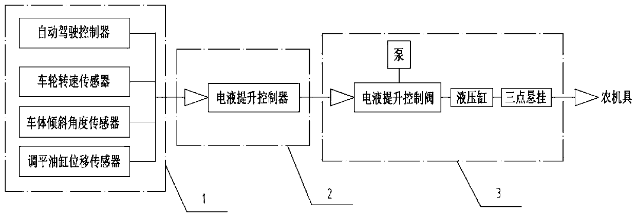
The invention discloses an intelligent electro-hydraulic lifting control device for a paddy field agricultural machine. The intelligent electro-hydraulic lifting control device comprises a detection module, a control module and an execution module. The control module makes an action judgment according to agricultural machine information acquired by the detection module and sends a signal. The execution module controls automatic lifting, lowering and leveling of agricultural implements. The detection module comprises an automatic driving controller, a wheel speed sensor, a body tilt angle sensor and a leveling cylinder displacement sensor. The control module comprises an electro-hydraulic lifting controller. The execution module comprises an electro-hydraulic lifting control valve, a pump,a hydraulic cylinder and a three-point suspension, and is used for executing instructions sent by the control module to control movement of the agricultural implements. The agricultural machine information includes a straight travelling signal, a turning and reversing signal and an agricultural implement leveling signal. The invention further discloses an intelligent electro-hydraulic lifting control method for the paddy field agricultural machine. Straight travelling of the paddy field agricultural machine, the tilling depth of the agricultural implements during turning and reversing, and automatic leveling of the agricultural implements in a paddy field can be controlled.

Description

technical field [0001] The invention relates to the field of agricultural machinery, in particular to an intelligent electro-hydraulic lifting control device and method for paddy field agricultural machinery. Background technique [0002] Most of the existing three-point suspension devices of tractors and agricultural implements are mechanical and manual operations, which have the following three problems: [0003] The first point: tractors operate in a straight line in paddy fields, and the slip rate is difficult to control so that traction efficiency and fuel economy control cannot be achieved; [0004] The second point: tractor paddy field operation until the field head turns around, it is necessary to manually control the lifting and lowering of agricultural machinery, such repeated operations seriously affect work efficiency and increase labor intensity; [0005] The third point: when tractor works in paddy fields, the left and right inclination angle of agricultural i...

Claims


Application Information

Patent Timeline
Patent Type & Authority Applications(China)
IPC IPC(8): A01B63/10A01B63/12
CPCA01B63/1006A01B63/12
Inventor 朱保江高一平贡军周璇德黄静吴悦
Owner ZOOMLION HEAVY MASCH CO LTD
Why Eureka
Eureka Blog
Learn More