A condenser back molding machine

A molding machine and condenser technology, applied in the directions of feeding devices, manufacturing tools, positioning devices, etc., can solve the problems of low work intensity of operators, low production efficiency, small scope of application, and high manufacturing costs, and improve the application. The effect of range, reduced work intensity, and low manufacturing cost

Active Publication Date: 2021-06-29
苏州威尔博机械有限公司
View PDF6 Cites 0 Cited by
  • Summary
  • Abstract
  • Description
  • Claims
  • Application Information

AI Technical Summary

Problems solved by technology

The condenser tube is an essential part of the condenser. When producing the condenser tube, it is necessary to bend the condenser tube to make the condenser tube play the role of condensing steam and condensing liquid droplets. However, most of the existing condensers are back-shaped When the machine is bent, the operator needs to manually control it, resulting in increased work intensity of the operator and low production efficiency, and the scope of application is not large, and the automation is not high. However, the existing automatic condenser return molding machine manufacturing The cost is high, for this reason, a condenser back molding machine is proposed

Method used


Image

  • A condenser back molding machine
  • A condenser back molding machine
  • A condenser back molding machine

Examples


Embodiment

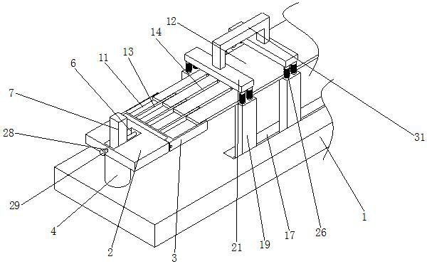
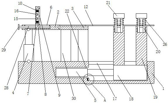
[0019] see Figure 1-3 , the present invention provides a technical solution: a condenser back molding machine, including a base 1, the bottom of the base 1 is hinged with a first cylinder 4, the piston rod of the first cylinder 4 is hinged with a first plate 2, the first The cylinder 4 drives the first plate body 2 to move upwards to bend the condensation pipe. The inside of the first plate body 2 is provided with a guide groove 6, and the inside of the guide groove 6 is slidingly connected to the limit rod 7, which can limit the bending length, one side of the first board 2 is hinged with a second board 3, the inside of the second board 3 is provided with a second groove 11, and the inside of the second groove 11 is slidably connected with a carrier board 12, through The second groove 11 guides and limits the stroke of the carrier plate 12, the limit rod 7 is provided with a first groove 8 on the side close to the second plate body 3, and the inside of the first groove 8 is ...


PUM


Abstract

The invention discloses a condenser back molding machine, which comprises a base, a first cylinder is hinged at the bottom of the base, a piston rod of the first cylinder is hinged with a first plate, and a first plate is hinged. A second plate is hinged on the side, and a second groove is opened inside the second plate, and a loading plate is slidably connected to the inside of the second groove, and the limit rod is close to the second plate. One side of the body is provided with a first groove, the inside of the first groove is slidably connected with a support plate, the inner side walls of the first groove are respectively riveted with a first switch and a second switch, the slider Two support rods are respectively welded on the top of both sides, and the top of the support rod is slidably connected with a connecting rod, and the end of the connecting rod far away from the support rod is fixedly connected with a pressure plate, which realizes semi-automatic production and low manufacturing cost , can reduce the cost of expenditure and the work intensity of the operator, and effectively improve the production efficiency.

Description

technical field [0001] The invention relates to the technical field of condenser pipe processing equipment, in particular to a condenser return molding machine. Background technique [0002] The condenser is a component of the refrigeration system and is a type of heat exchanger that can convert gas or vapor into liquid, and transfer the heat in the tube to the air near the tube in a very fast manner. The working process of the condenser is an exothermic process, so the temperature of the condenser is relatively high. The condenser tube is an essential part of the condenser. When producing the condenser tube, it is necessary to bend the condenser tube to make the condenser tube play the role of condensing steam and condensing liquid droplets. However, most of the existing condensers are back-shaped When the machine is bent, the operator needs to manually control it, which leads to the increase of the operator's work intensity and low production efficiency, and the scope of ...

Claims


Application Information

Patent Timeline
Patent Type & Authority Patents(China)
IPC IPC(8): B21D7/022B21D43/00B21D53/06
CPCB21D7/022B21D43/003B21D53/06
Inventor 刘志勇
Owner 苏州威尔博机械有限公司
Why Eureka
Try Eureka