Flexible collaborative robot modular joint
A technology of modular joints and robots, applied in the directions of manipulators, manufacturing tools, joints, etc., can solve the problems of cable wear and poor design flexibility, and achieve the effect of large load self-weight, reduce processing costs, and increase design flexibility.
- Summary
- Abstract
- Description
- Claims
- Application Information
AI Technical Summary
Problems solved by technology
Method used
Image

Examples
specific Embodiment approach 1
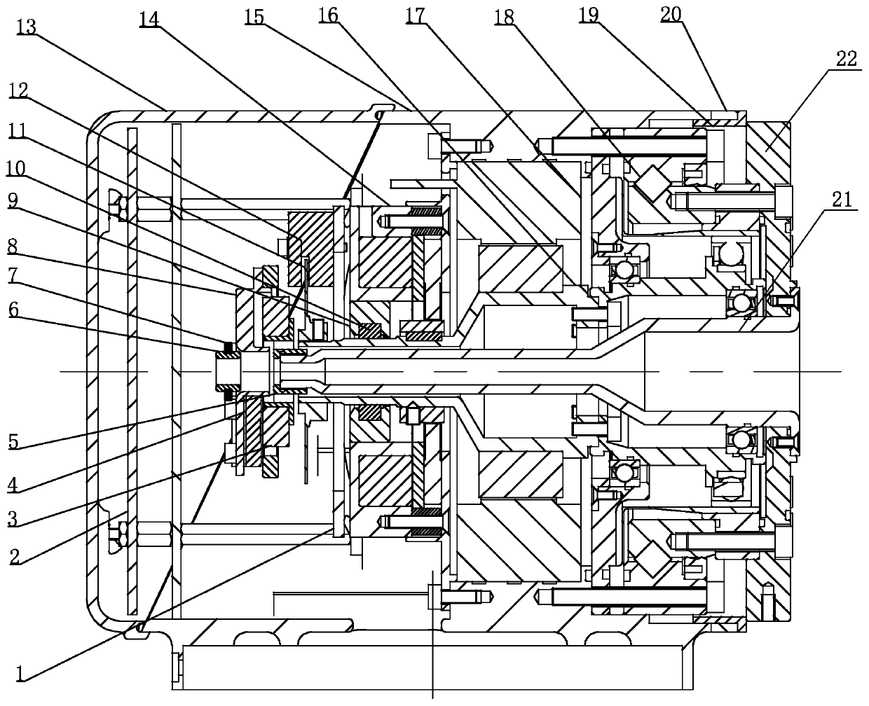
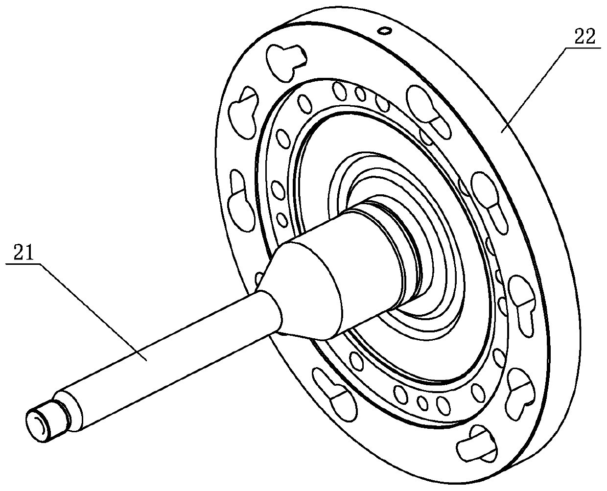
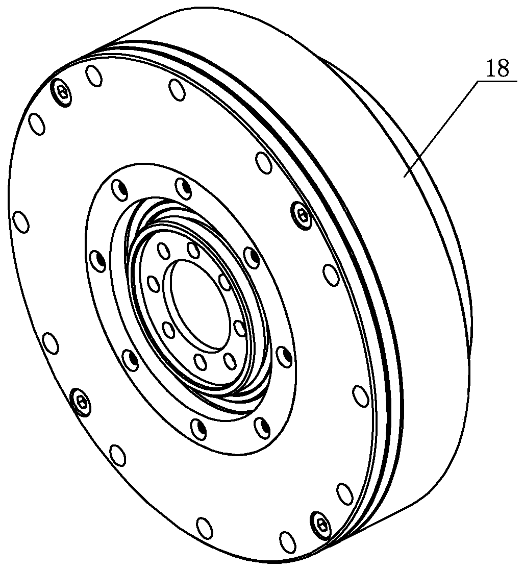
[0031] Specific implementation mode one: combine Figure 1 to Figure 5 Describe this embodiment, a modular joint of a flexible collaborative robot in this embodiment includes a joint housing 15; End encoder reading head 4, joint end encoder code disk mounting seat 5, joint end encoder reading head mounting seat 8, motor end encoder code disc 11, motor end encoder reading head 12, rear cover 13, brake assembly 14 , motor assembly 17, harmonic reducer 18, protective pipe 21 and output flange 22; the motor assembly 17 and harmonic reducer 18 are installed in the joint housing 15 in sequence from left to right, and the motor assembly 17 and the harmonic The input end of the reducer 18 is connected, the output flange 22 is installed on the output end of the harmonic reducer 18, the wire protection tube 21 is passed through the motor shaft 16 of the motor assembly 17 and connected with the output flange 22, the brake assembly 14 Installed in the joint housing 15 and on the left sid...
specific Embodiment approach 2
[0040] Specific implementation mode two: combination figure 1 Describe this embodiment, the motor assembly 17 of this embodiment includes a motor stator, a motor rotor and a motor shaft 16, the motor stator is fixedly mounted on the inner side wall of the joint housing 15, and the motor shaft 16 is horizontally installed in the joint housing 15, The motor rotor is located between the motor stator and the motor shaft 16 , and the motor rotor is fixedly connected to the motor shaft 16 . Set up in this way, it is easy to provide enough power to the joint. Other compositions and connections are the same as in the first embodiment.
[0041] The motor shaft 16 in this embodiment is a hollow stepped shaft.
specific Embodiment approach 3
[0042] Specific implementation mode three: combination figure 1 The present embodiment will be described. The brake assembly 14 of the present embodiment is a magnetic friction brake. In this way, the brake assembly of this embodiment is a magnetic suction friction type. When the power is off, the brake locks the friction plate through the built-in spring, and the motor shaft cannot rotate through the brake hub; Contact brake: due to the friction brake principle, when the robot stops suddenly, it is safer and more reliable than the pin brake. There is no problem of bent pins and shaking joints when powered on. Other compositions and connections are the same as those in Embodiment 1 or Embodiment 2.
PUM
 Abstract
Description
Claims
Application Information
 - R&D
- Intellectual Property
- Life Sciences
- Materials
- Tech Scout
- Unparalleled Data Quality
- Higher Quality Content
- 60% Fewer Hallucinations
Browse by: Latest US Patents, China's latest patents, Technical Efficacy Thesaurus, Application Domain, Technology Topic, Popular Technical Reports.
© 2025 PatSnap. All rights reserved.Legal|Privacy policy|Modern Slavery Act Transparency Statement|Sitemap|About US| Contact US: help@patsnap.com