Turbine blade trailing edge fold line type exhaust split seam structure

A turbine blade and trailing edge technology, which is applied in the direction of blade support components, engine components, machines/engines, etc., can solve problems such as large flow resistance, low cooling effect, and damage to blade structural strength, so as to achieve smooth flow and reduce flow Effects of resistance, loss, and efficiency improvement

Active Publication Date: 2020-02-04
DALIAN UNIV OF TECH
View PDF6 Cites 4 Cited by
  • Summary
  • Abstract
  • Description
  • Claims
  • Application Information

AI Technical Summary

Problems solved by technology

This kind of trailing edge slit cooling structure has greater flow resistance and lower cooling effect, and also has a certain damage to the structural strength of the blade

Method used


Image

  • Turbine blade trailing edge fold line type exhaust split seam structure
  • Turbine blade trailing edge fold line type exhaust split seam structure
  • Turbine blade trailing edge fold line type exhaust split seam structure

Examples


Embodiment 1

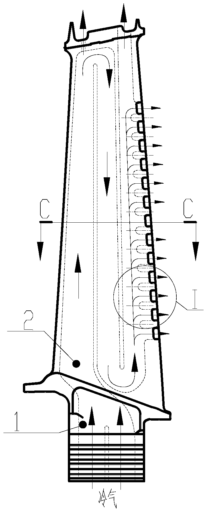
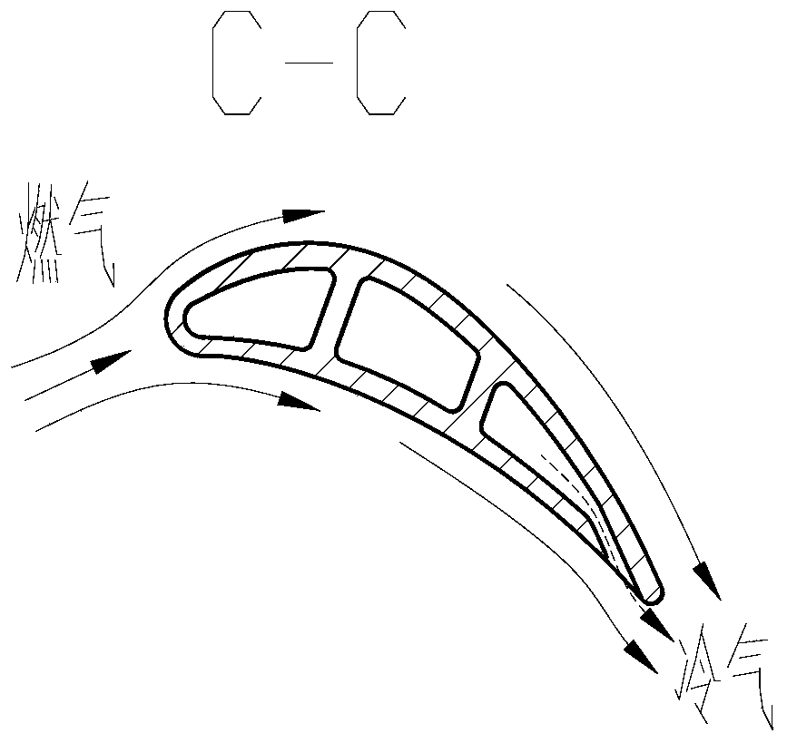
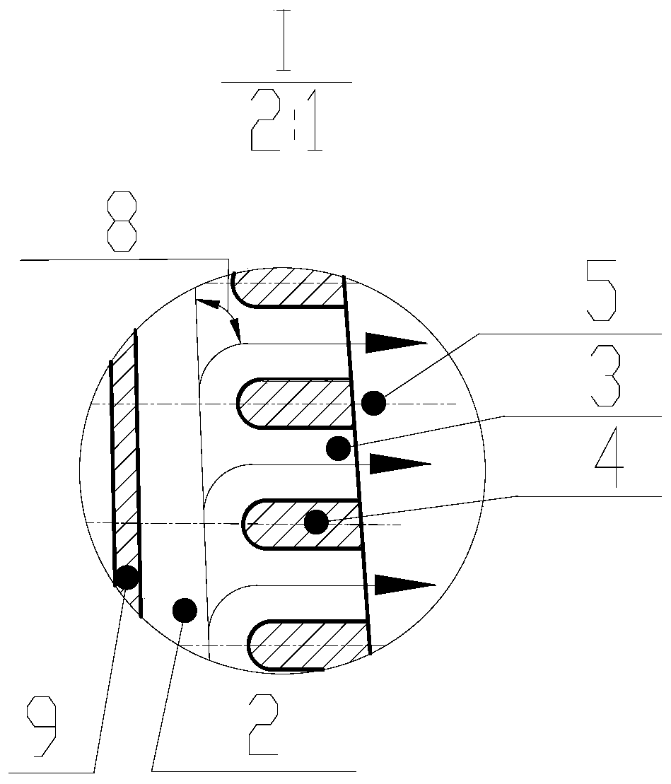
[0036] Please refer to FIG. 2 , a turbine blade trailing edge broken-line exhaust splitting structure, including a hollow turbine blade 1, an inner cavity cold air channel 2, a trailing edge exhaust splitting channel 3 and a trailing edge splitting rib 4;

[0037] The interior of the hollow turbine blade 1 is provided with an inner cavity cold air passage 2, and the trailing edge of the hollow turbine blade 1 is provided with side-by-side trailing edge split ribs 4, and the trailing edge split ribs 4 arranged side by side form a trailing edge row The gas splitting channel 3, the structure of the trailing edge splitting rib 4 forms a broken line shape, and its shape is controlled by the center line 5 of the rib, and the center line 5 of the rib is connected by at least two line segments with different angles, and wherein At least one section is inclined relative to the horizontal plane, and the width of the split rib 4 at the trailing edge is symmetrically distributed along the ...

Embodiment 2

[0039] Please refer to FIG. 2 , a turbine blade trailing edge broken-line exhaust splitting structure, including a hollow turbine blade 1, an inner cavity cold air channel 2, a trailing edge exhaust splitting channel 3 and a trailing edge splitting rib 4;

[0040] The interior of the hollow turbine blade 1 is provided with an inner cavity cold air passage 2, and the trailing edge of the hollow turbine blade 1 is provided with side-by-side trailing edge split ribs 4, and the trailing edge split ribs 4 arranged side by side form a trailing edge row The gas splitting channel 3, the structure of the trailing edge splitting rib 4 forms a broken line shape, and its shape is controlled by the center line 5 of the rib, and the center line 5 of the rib is connected by at least two line segments with different angles, and wherein At least one section is inclined relative to the horizontal plane, and the width of the split rib 4 at the trailing edge is symmetrically distributed along the ...

Embodiment 3

[0042] Please refer to FIG. 2 , a turbine blade trailing edge broken-line exhaust splitting structure, including a hollow turbine blade 1, an inner cavity cold air channel 2, a trailing edge exhaust splitting channel 3 and a trailing edge splitting rib 4;

[0043] The interior of the hollow turbine blade 1 is provided with an inner cavity cold air passage 2, and the trailing edge of the hollow turbine blade 1 is provided with side-by-side trailing edge split ribs 4, and the trailing edge split ribs 4 arranged side by side form a trailing edge row The gas splitting channel 3, the structure of the trailing edge splitting rib 4 forms a broken line shape, and its shape is controlled by the center line 5 of the rib, and the center line 5 of the rib is connected by at least two line segments with different angles, and wherein At least one section is inclined relative to the horizontal plane, and the width of the split rib 4 at the trailing edge is symmetrically distributed along the ...


PUM


Abstract

The invention belongs to the technical field of aero-engine turbine cooling, and relates to a turbine blade trailing edge fold line type exhaust split seam structure. The turbine blade trailing edge fold line type exhaust split seam structure comprises a hollow turbine blade, an inner cavity cold air channel, a trailing edge exhaust split seam channel and trailing edge split seam partition ribs, wherein the inner cavity cold air channel is formed in the hollow turbine blade, and low-temperature cooling gas flows in the blade to cool the blade; the trailing edge split seam partition ribs arranged side by side are arranged on the trailing edge of the hollow turbine blade; and the trailing edge exhaust split seam channel is formed between the trailing edge split seam partition ribs arranged side by side. According to the turbine blade trailing edge fold line type exhaust split seam structure, a trailing edge exhaust split seam is designed into an inclined fold line type exhaust mode, theturning angle of the cooling gas in the split seam is reduced, and cold air is turned twice or multiple times instead of being turned once, so that the flow resistance and loss of the cold air in an inner cavity of the blade are reduced, and the flow resistance can be reduced by about 19%.

Description

technical field [0001] The invention belongs to the technical field of aero-engine turbine cooling, and relates to a broken-line exhaust slit structure at the trailing edge of a turbine blade. Background technique [0002] Increasing the gas temperature before the turbine can greatly improve the efficiency of aero-engines and gas turbines, but the current gas temperature before the turbine has far exceeded the limit of the materials used, so it is urgent to develop more effective turbine blade cooling technology. At present, the hollow design is generally adopted for the turbine blades, and the heat is taken away by the enhanced convection heat transfer of the cooling gas inside and the air film is formed to cover and isolate the gas heating when the blades are discharged. This is the main solution to the cooling problem of the turbine blades. Larger internal heat exchange area", "smaller cold air flow resistance", "higher heat exchange efficiency", "larger air film coverage...

Claims


Application Information

Patent Timeline
Patent Type & Authority Applications(China)
IPC IPC(8): F01D5/18
CPCF01D5/188
Inventor 吕东周亦胄王晓放孔星傲王楠
Owner DALIAN UNIV OF TECH
Why Eureka
Try Eureka