Arrangement of a Parking Lock in a Vehicular Transmission

A technology for arranging structure and locking device, which is applied to vehicle parts, transmission parts, transmission control, etc., can solve the problem of increasing the installation space of the control device, and achieve the effect of saving installation space

Active Publication Date: 2020-02-04
ZF FRIEDRICHSHAFEN AG
View PDF8 Cites 0 Cited by
  • Summary
  • Abstract
  • Description
  • Claims
  • Application Information

AI Technical Summary

Problems solved by technology

As a result, the required installation space for the control unit increases

Method used


Image

  • Arrangement of a Parking Lock in a Vehicular Transmission
  • Arrangement of a Parking Lock in a Vehicular Transmission
  • Arrangement of a Parking Lock in a Vehicular Transmission

Examples


Embodiment Construction

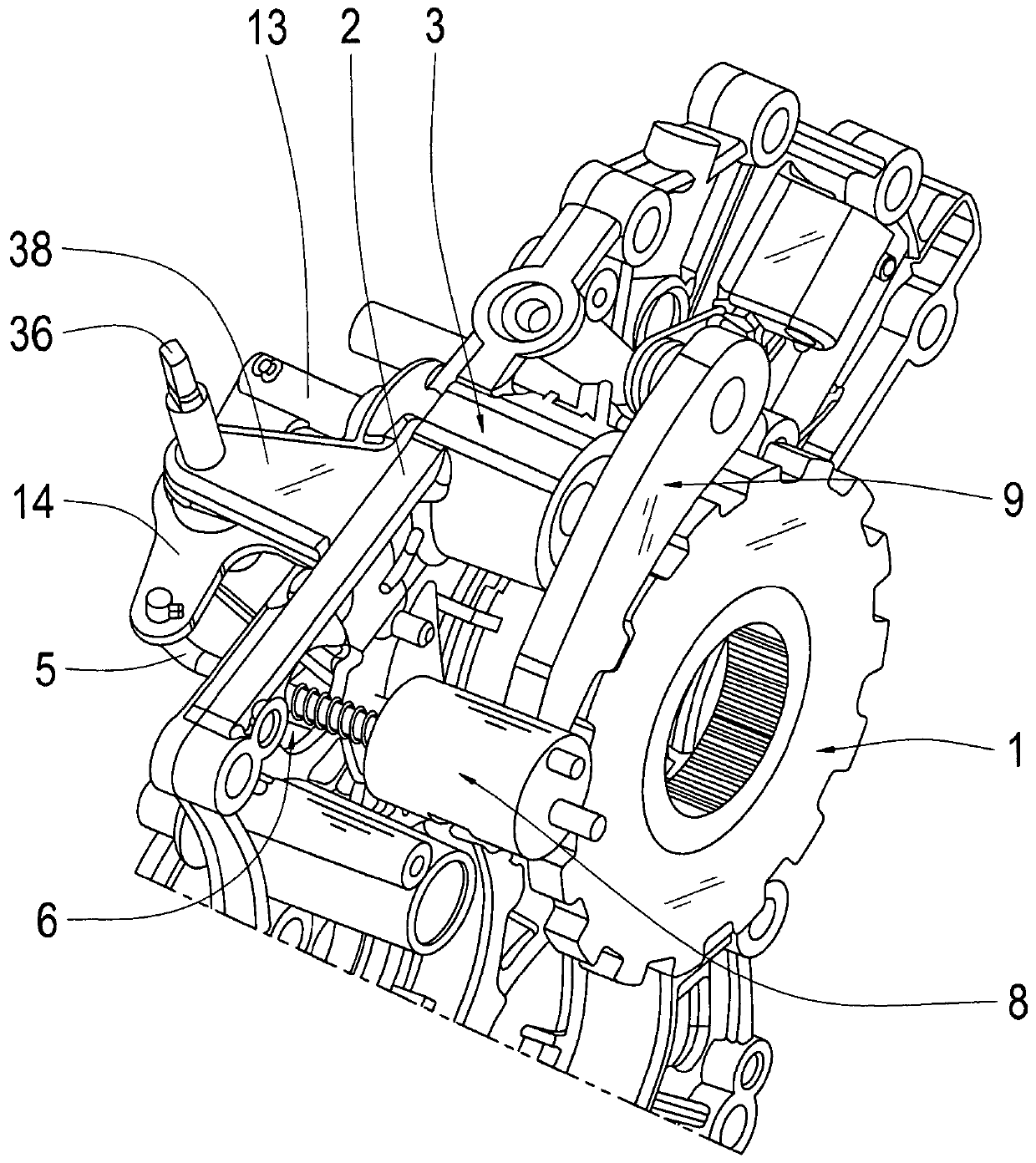
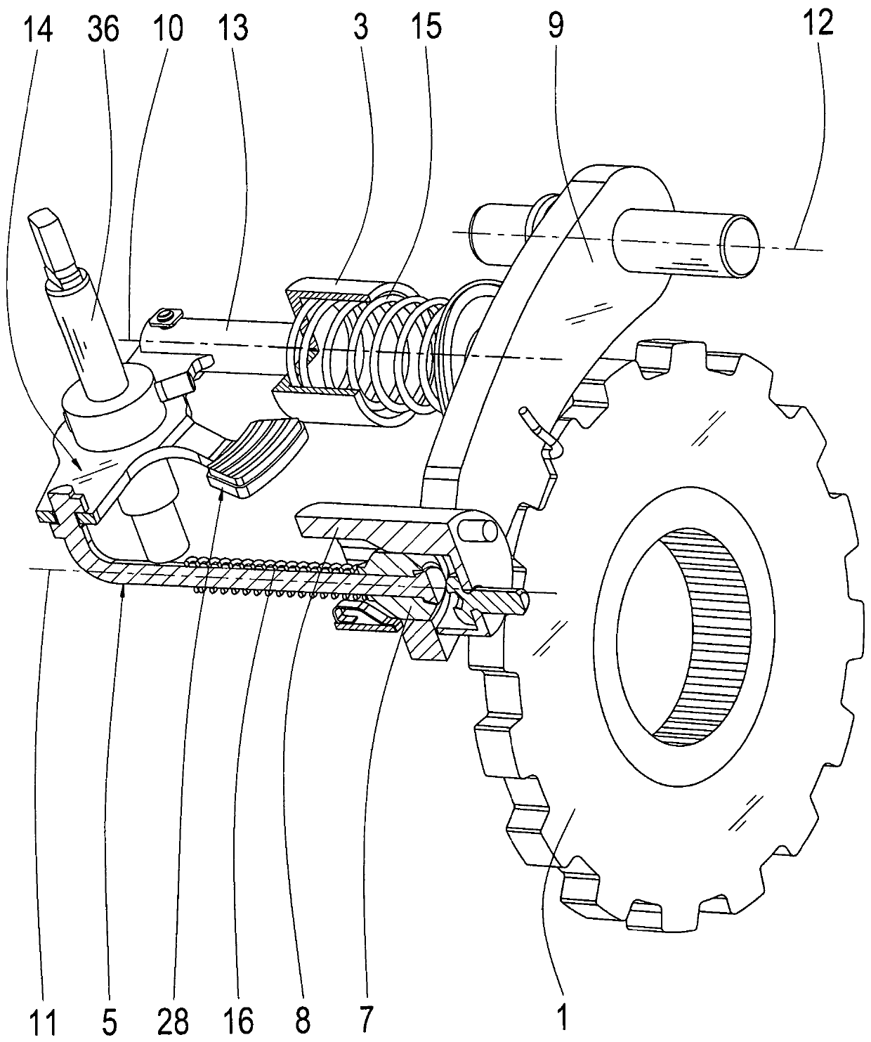
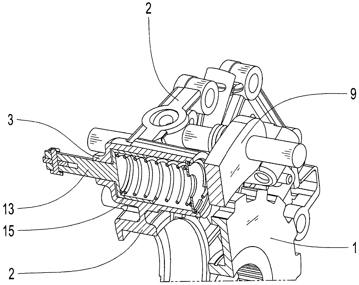
[0019] exist Figures 1 to 7 Different views of a possible arrangement according to the invention of the parking lock device on the intermediate plate 2 of the vehicle transmission are shown by way of example in FIG.

[0020] It is provided within the scope of the arrangement according to the invention that the parking lock has a locking mechanism and an actuating device for locking and releasing the parking lock wheel 1 . The actuating device is coupled to the locking mechanism via a coupling mechanism for actuating the locking mechanism between a locked position and a released position of the parking lock wheel 1 . According to the invention it is provided that the parking lock device is arranged on the intermediate wall or intermediate wall 2 in a housing of the vehicle transmission which is not further shown here.

[0021] especially by figure 1 It can be seen that the actuating device and the coupling mechanism are integrated into the intermediate plate 2 . In this cas...


PUM


Abstract

The invention relates to an arrangement of a parking lock in a vehicular transmission. A parking lock in a vehicle transmission includes a locking mechanism for locking and releasing a parking interlock gear (1) and an actuating unit. The actuating unit is coupled via a coupling mechanism to the locking mechanism in order to actuate the locking mechanism between an interlock position and a releaseposition of the parking interlock gear (1). The parking lock is arranged on an intermediate plate (2) in a housing of the vehicle transmission.

Description

technical field [0001] The invention relates to an arrangement of a parking lock device in a vehicle transmission of the type defined in detail in the preamble of claim 1 . Background technique [0002] A parking lock device for a motor vehicle transmission is known, for example, from document DE 10 2016 101 486 A1. The parking lock device has a locking pawl for securing the output shaft of the transmission coupled to the parking locking wheel, wherein the locking pawl can be moved between an open position (or a released position) and a locked position of the parking locking wheel by means of an actuating device. sports. The actuating device is embodied as a hydraulic cylinder arrangement, which is coupled to a mechanical step tilting device, which is connected between the hydraulic cylinder arrangement and the locking mechanism. The hydraulic cylinder arrangement has a cylinder and an axially displaceable piston in the cylinder, which is coupled to a stepped tilting devic...

Claims


Application Information

Patent Timeline
Patent Type & Authority Applications(China)
IPC IPC(8): F16H63/38
CPCF16H63/38B60T1/005F16D63/006B60T1/062F16H63/3425F16H57/00F16H63/3483F16H61/0003F16H2057/0216B60T7/045B60T8/3215F16H63/3433F16H63/3441
Inventor G·汉克C·米歇尔
Owner ZF FRIEDRICHSHAFEN AG
Why Eureka
Try Eureka