Pressure-maintaining core sampler flap valve with multi-stage sealing structure

A technology of sealing structure and corer, which is applied in the direction of lift valve, valve device, mechanical equipment, etc., can solve the problems of easy sealing failure, leakage of corer, and inability to maintain pressure, so as to improve the anti-deformation ability and avoid pressure. Leakage, the effect of preventing valve leakage

Pending Publication Date: 2020-02-04
SHENZHEN UNIV
View PDF0 Cites 8 Cited by
  • Summary
  • Abstract
  • Description
  • Claims
  • Application Information

AI Technical Summary

Problems solved by technology

The structure of the ball valve is relatively complex and occupies a large space, which limits the diameter of the drilled core. The processing technology of the ball valve is high, and when the pressure is high, the liquid in the pressure-holding cylinder will leak from the gap between the ball valve and the core cylinder. inability to maintain high pressure
Although the existing flap valve has a simple structure, it uses a single sealing ring for sealing. If one of the sealing rings leaks, it will cause the liquid in the core remover to leak and damage the pressure-holding performance of the core remover; Some flap valves are prone to seal failure in high temperature and high pressure environments

Method used


Image

  • Pressure-maintaining core sampler flap valve with multi-stage sealing structure
  • Pressure-maintaining core sampler flap valve with multi-stage sealing structure
  • Pressure-maintaining core sampler flap valve with multi-stage sealing structure

Examples


Embodiment 1

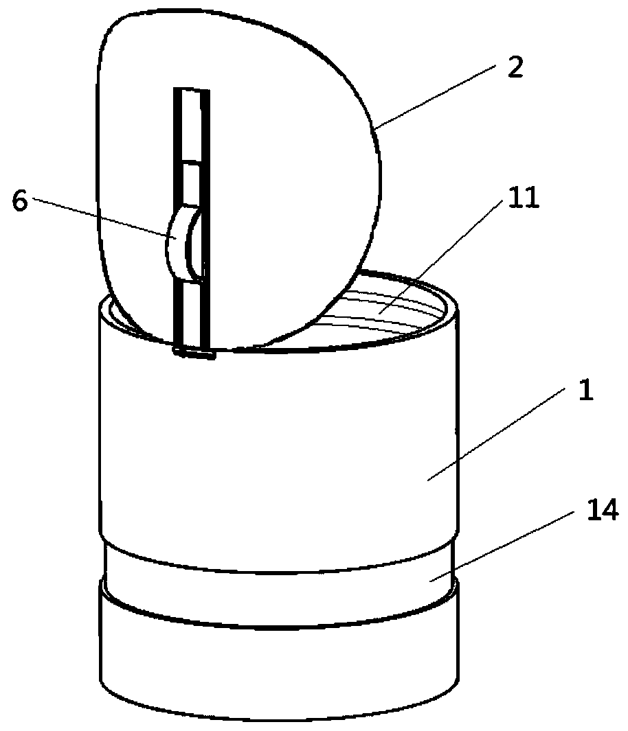
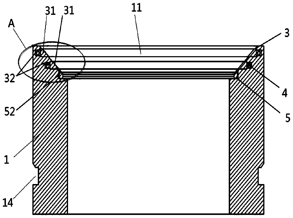
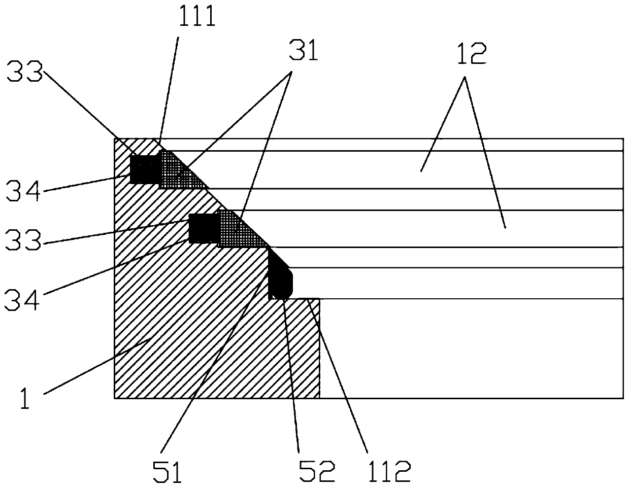
[0032] Such as figure 1 As shown, the pressure-maintaining core remover flap valve with a multi-stage sealing structure disclosed in this embodiment includes a valve seat 1 and a valve disc 2, one end of the valve disc 2 is movably connected to the upper end of the valve seat 1, and the valve disc 2 is connected by a spring plate 6 and the rotating shaft are movably connected on the valve seat 1, and the outer wall of the top end of the valve seat 1 has a rotating shaft accommodation groove that matches the rotating shaft, and the rotating shaft is installed in the rotating shaft accommodation groove, and the outer surface of the valve disc 2 has a shrapnel for accommodating the spring piece 6 Accommodating groove, spring leaf 6 is contained in the shrapnel accommodating groove. The spring piece 6 is a curved steel piece, which is stuck in the shrapnel holding groove, and the curved steel piece can be straightened under the action of an external force, and its curved surface c...

Embodiment 2

[0046] Since the traditional core taker flap valve is triggered by the shrapnel and relies on the gravity of the valve disc to realize the cooperative action, it can only drill in near-vertical conditions.

[0047] Therefore, in this embodiment, a magnet is provided on the valve seat 1 , and a magnetic material is provided on the valve disc 2 . The magnet can be an NdFeB magnet, and the disc 2 is made of 20CrMnMo carburizing steel. The shape, position and quantity of the magnets are set as required. This embodiment only mentions two of them, but is not limited to these two configurations.

[0048] The first type, such as Figure 7 As shown, an annular magnet 6 is installed on the valve seat 1, and the position of the annular magnet 6 is set as required. The annular magnet 6 can be arranged below the sealing groove 16 of the valve seat, and can also be arranged above the sealing groove 16 of the valve seat.

[0049] The second type, such as Figure 8 As shown, the sheet ma...


PUM


Abstract

The invention relates to a pressure-maintaining core sampler flap valve with a multi-stage sealing structure. The pressure-maintaining core sampler flap valve comprises a valve seat and a valve clack;one end of the valve clack is movably connected with the upper end of the valve seat; a valve opening which is matched with the valve clack is formed in the top of the valve seat, and when the valveclack is closed, at least two sealing pairs are formed between the valve seat and the valve clack; sealing between the valve seat and the valve clack includes hard sealing and soft sealing; at least two sealing parts are arranged in the valve opening of the valve seat; the first sealing part comprises a metal sealing ring and a U-shaped sealing structure; and when the valve clack is closed, the valve clack and the metal sealing ring are in contact to form hard sealing, and meanwhile the valve clack makes the metal sealing ring expand so as to squeeze the U-shaped sealing structure to form softsealing. The valve seat and the valve clack adopt the multi-stage sealing structure, the sealing property is reliable, multi-line / plane sealing contact is achieved, and thus valve leakage can be effectively prevented; the deformation resistance of an airtight surface can be effectively improved through the expandable property of the metal sealing ring, during pressing, deformation of the pressedvalve clack and valve seat can be compensated, pressure leakage is avoided, and the pressure-maintaining core sampler flap valve is applicable to the high-temperature and high-pressure working conditions.

Description

technical field [0001] The invention relates to the technical field of sealing devices for core removers, in particular to a flap valve for pressure maintaining core removers with a multi-stage sealing structure. Background technique [0002] At present, in the field of pressure-holding coring, the upper end of the pressure-holding cylinder is generally sealed by a piston, and the lower end of the pressure-holding cylinder is usually sealed by a ball valve or a flap valve. The structure of the ball valve is relatively complex and occupies a large space, which limits the diameter of the drilled core. The processing technology of the ball valve is high, and when the pressure is high, the liquid in the pressure-holding cylinder will leak from the gap between the ball valve and the core cylinder. Unable to maintain high pressure. Although the existing flap valve has a simple structure, it uses a single sealing ring for sealing. If one of the sealing rings leaks, it will cause t...

Claims


Application Information

Patent Timeline
Patent Type & Authority Applications(China)
IPC IPC(8): F16K1/20F16K1/46
CPCF16K1/20F16K1/2042
Inventor 谢和平高明忠陈领张志龙吴年汉李聪李佳南何志强杨明庆余波胡云起黄伟
Owner SHENZHEN UNIV
Why Eureka
Try Eureka