
Steel pipe cutting equipment for house-building project

A kind of cutting equipment and engineering technology, which is applied in the field of steel pipe cutting equipment for housing construction projects, can solve the problems of cutting saw blade breakage, difficult problems, complicated operation, etc., and achieve the effect of avoiding breakage and improving efficiency

Active Publication Date: 2020-02-07
NINGBO CONSTR GRP
View PDF8 Cites 2 Cited by
  • Summary
  • Abstract
  • Description
  • Claims
  • Application Information

AI Technical Summary

Problems solved by technology

[0003] However, the following problems exist in the cutting process of existing steel pipes for building construction. A. During the cutting process of steel pipes, it is necessary to manually use fixing tools to fix the steel pipes. broken
b. For steel pipes of different specifications, it is necessary to prepare corresponding fixing tools, and in the continuous cutting operation, it is necessary to manually control the movement of the steel pipes. It is necessary to manually control the fixing tools to tighten the steel pipes frequently. The operation is complicated, which reduces the efficiency of steel pipe cutting and processing
[0004] For the technical problems existing in steel pipe cutting in house construction, personnel in the relevant technical fields have made adaptation improvements after research, such as the Chinese utility model patent No. 2017208604704, a steel pipe cutting jig, which can increase the cutting time of steel pipes. The utilization rate of feeding materials, however, did not mention the problems existing in the cutting of steel pipes in the construction of existing houses mentioned above

Method used


Image

  • Steel pipe cutting equipment for house-building project
  • Steel pipe cutting equipment for house-building project
  • Steel pipe cutting equipment for house-building project

Examples


Embodiment Construction

[0023] The embodiments of the present invention will be described in detail below with reference to the accompanying drawings, but the present invention can be implemented in many different ways defined and covered by the claims.

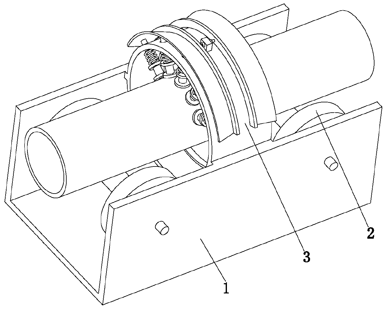
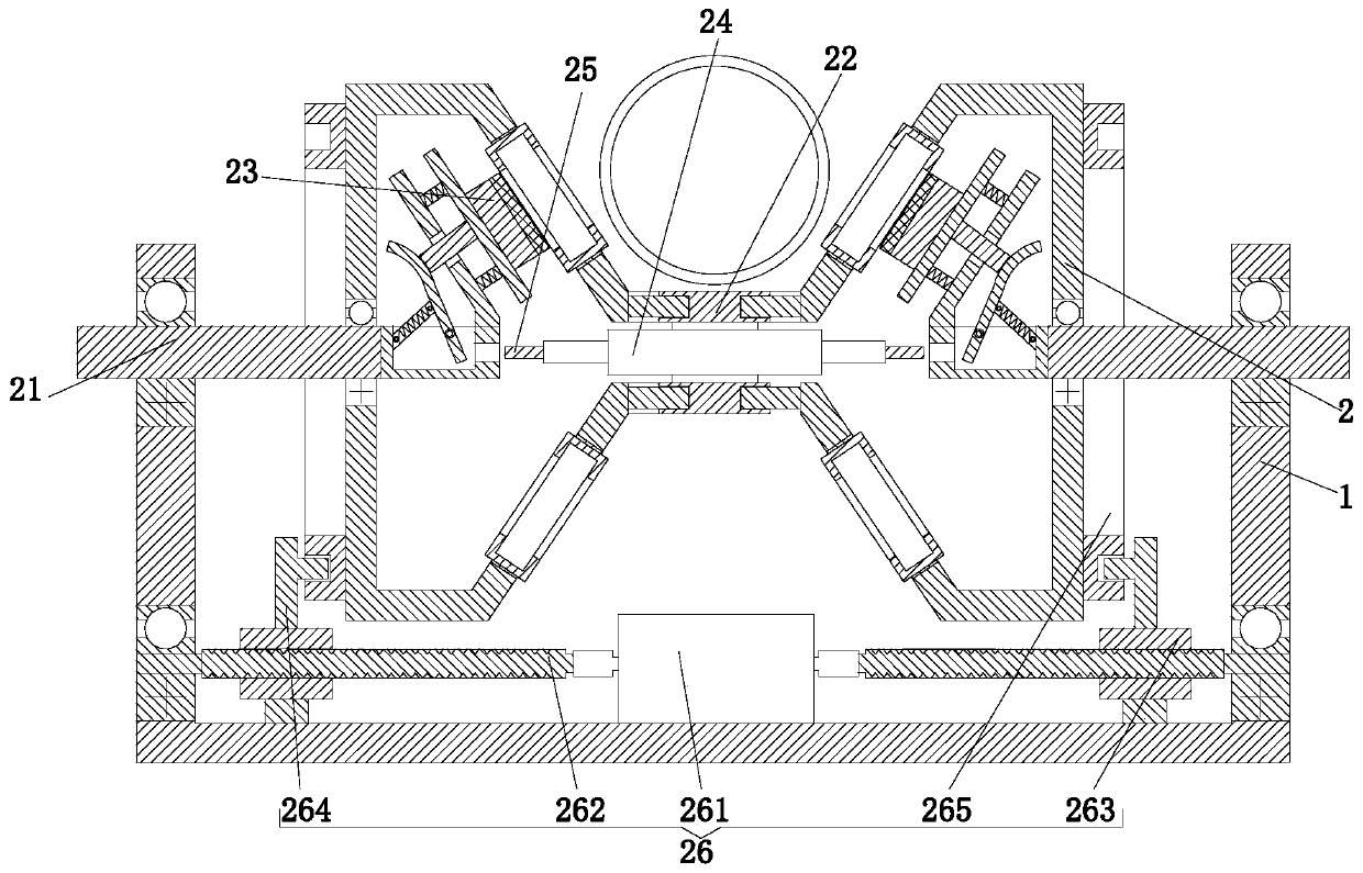
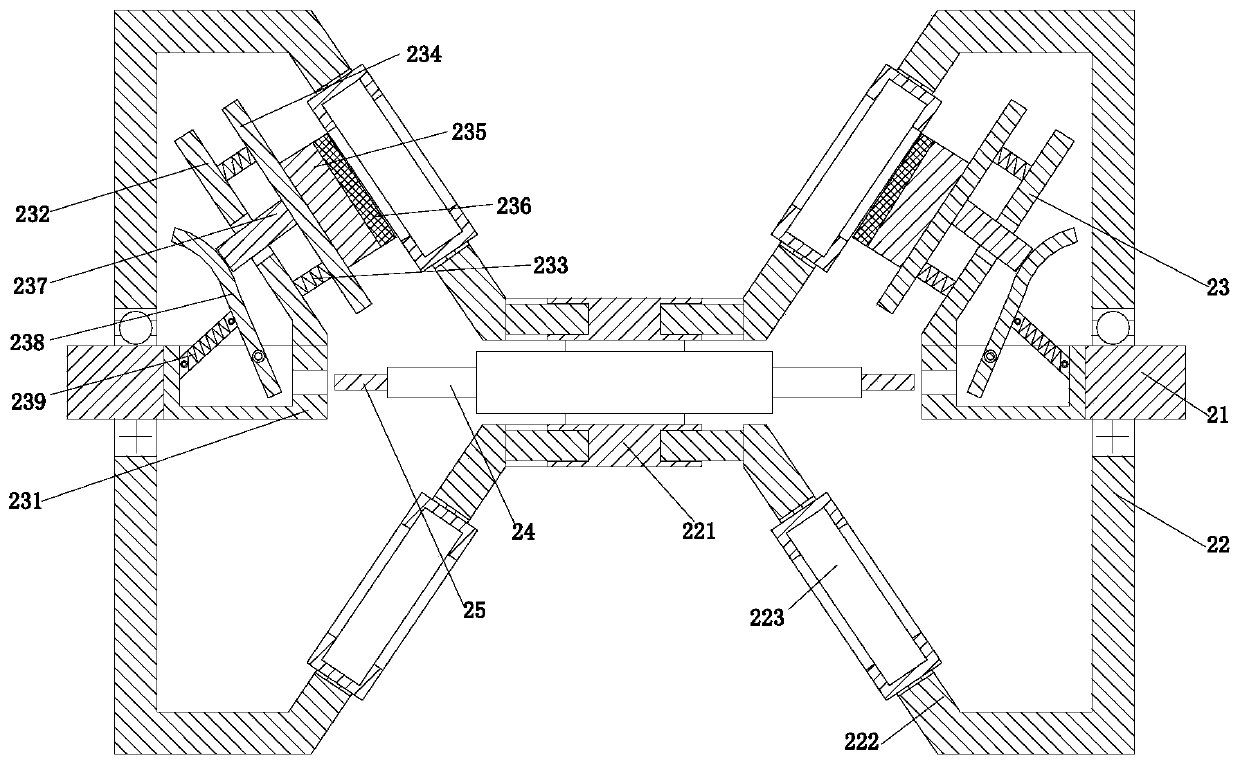
[0024] Such as Figure 1 to Figure 4 As shown in the figure, a steel pipe cutting equipment for house construction includes a cutting base frame 1, auxiliary mechanisms 2 are symmetrically arranged on the front and rear sides of the cutting base frame 1, and a cutting mechanism 3 is installed in the middle of the cutting base frame 1.

[0025] The auxiliary mechanism 2 includes support shafts 21 symmetrically installed on the left and right sides of the cutting base frame 1 through bearings. Auxiliary rollers 22 are installed between the support shafts 21 through linear bearings. The auxiliary rollers 22 are hollow structures. One end of the inner side of 22 is provided with positioning branch chain 23, and the two-way positioning cylinder 24 on the...


PUM


Abstract

The invention relates to steel pipe cutting equipment for a house-building project. The steel pipe cutting equipment comprises a cutting base frame, wherein auxiliary mechanisms are symmetrically arranged on the front side and the rear side of the cutting base frame, and a cutting mechanism is mounted in the middle of the cutting base frame. The steel pipe cutting equipment can solve the followingproblems existing in the cutting process of an existing steel pipe for house building that a, fixing tool using manually is needed to fix the steel pipe in the cutting process of the steel pipe, thestability of the manually-fixed steel pipe is poor, the steel pipe in the cutting operation shakes, and a cutting saw blade is easy to break; and b, the corresponding fixing tool needs to be preparedfor steel pipes with different specifications, the manual control of the steel pipe is required to move in the continuous cutting operation, the manual frequent control of the fixing tool is needed toloosen and tighten the steel pipe, the operation is complicated, and the cutting and machining efficiency of the steel pipe is reduced.

Description

technical field [0001] The invention relates to the technical field of steel pipe cutting, in particular to a steel pipe cutting equipment for house construction projects. Background technique [0002] House construction requires a lot of building materials, especially steel structure houses need to use a lot of steel pipes in the construction process. The length and specifications of steel pipes at different positions in the construction process are different, so targeted cutting processing is required In the cutting process, long steel pipes are used to cut short steel pipes of required specifications. At present, most steel pipes are processed by manual cutting. [0003] However, the following problems exist in the cutting process of existing steel pipes for building construction. A. During the cutting process of steel pipes, it is necessary to manually use fixing tools to fix the steel pipes. broken. b. For steel pipes of different specifications, it is necessary to pr...

Claims


Application Information

Patent Timeline
IPC IPC(8): B23D45/12B23D47/04
CPCB23D45/126B23D47/04
Inventor 谈荣赋黄勤
Owner NINGBO CONSTR GRP
Features
  • Generate Ideas
  • Intellectual Property
  • Life Sciences
  • Materials
  • Tech Scout
  • Unparalleled Data Quality
  • Higher Quality Content
  • 60% Fewer Hallucinations
Learn More