Automatic welding equipment

An automatic welding and equipment technology, applied in welding equipment, metal processing equipment, electric heating devices, etc., can solve the problems of poor welding effect and easy sliding of the bearing platform, so as to facilitate welding work, avoid inertial effect, and enhance blocking effect. Effect

Inactive Publication Date: 2020-02-07
王晨曦
View PDF0 Cites 2 Cited by
  • Summary
  • Abstract
  • Description
  • Claims
  • Application Information

AI Technical Summary

Problems solved by technology

[0005] The purpose of the present invention is to provide an automatic welding equipment to solve the problems

Method used


Image

  • Automatic welding equipment
  • Automatic welding equipment
  • Automatic welding equipment

Examples


Embodiment Construction

[0030] It should be understood that the specific embodiments described here are only used to explain the present invention, not to limit the present invention.

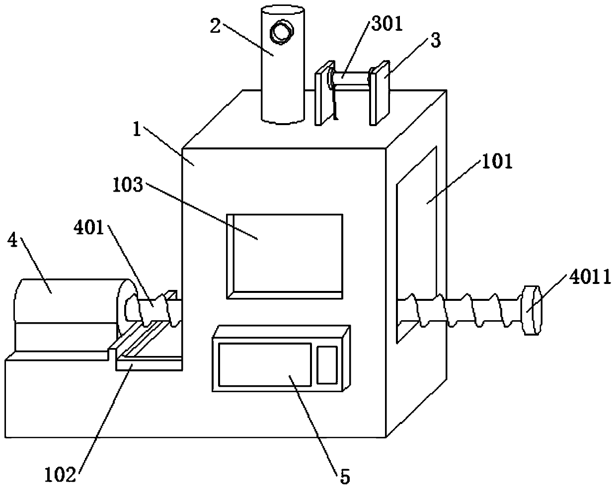
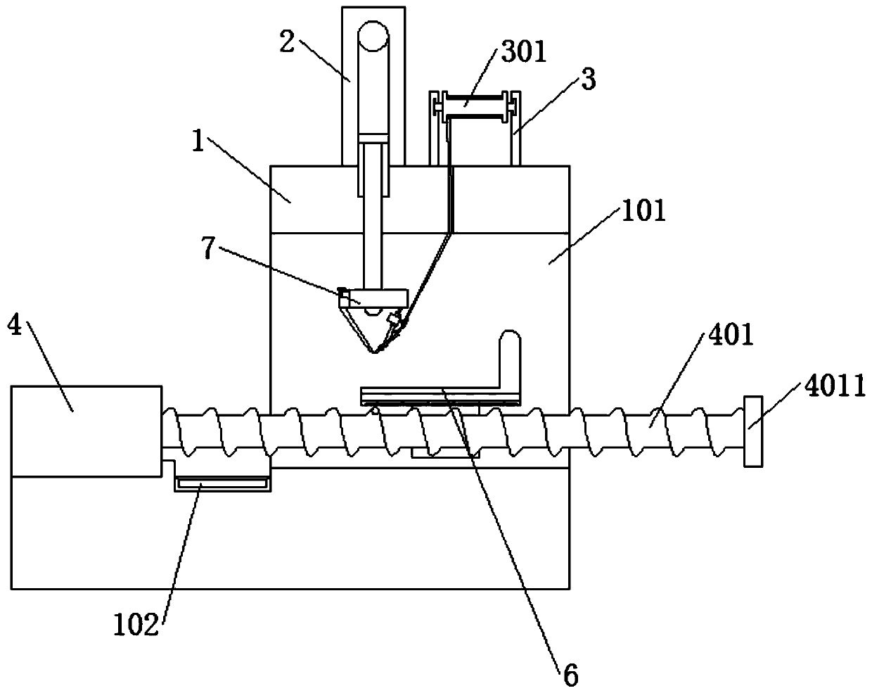
[0031] see figure 1 to attach Figure 8 , an automatic welding equipment, including: a shell 1, an electric cylinder 2, a support frame 3, a winding roller 301, a motor 4, a programmable controller 5, an electromagnetic steel plate 6 and a carrying plate 7, the top left of the shell 1 An electric cylinder 2 is arranged on the side, a supporting frame 3 is installed on the right side of the top of the housing 1, and a winding roller 301 is installed in the middle of the supporting frame 3, a motor 4 is installed on the top left side of the housing 1, and a motor 4 is installed on the bottom of the front end of the housing 1. The programming controller 5 is provided with an electromagnetic steel plate 6 inside the housing 1 , and a carrying plate 7 is provided at the bottom of the electric cylinder 2 .

[0032] see ...


PUM


Abstract

The invention provides automatic welding equipment. The equipment comprises a shell, an electric air cylinder, a supporting frame, a winding roller, a motor, a programmable logic controller, an electromagnetic steel plate and a bearing disc, wherein the electric air cylinder is arranged on the left side of the top of the shell, the supporting frame is arranged on the right side of the top of the shell, the winding roller is arranged in the middle of the supporting frame, the motor is arranged at the top of the left side of the shell, the programmable logic controller is arranged at the bottomof the front end of the shell, the electromagnetic steel plate is arranged on the inner side of the shell, and the bearing disc is arranged at the bottom of the electric air cylinder. The whole automatic welding equipment is stable in structure, high in welding precision, convenient to use and operate, stable during installation and smooth in movement, and can effectively avoid the situation thata welding bearing platform moves greatly.

Description

technical field [0001] The invention belongs to the technical field of welding equipment, and in particular relates to an automatic welding equipment. Background technique [0002] Welding, also known as welding and welding, is a manufacturing process and technology for joining metals or other thermoplastic materials by means of heating, high temperature or high pressure. There are many energy sources for modern welding, including gas flame, electric arc, laser, Electron beam, friction and ultrasonic, etc. In addition to being used in factories, welding can also be carried out in a variety of environments, such as the field, underwater and space. Welding uses low-melting point media and utilizes the capillary phenomenon between metals, so that molten tin can be stained between the two metals. The bonding effect of the surface makes it possible to conduct current. [0003] But the current welding is generally done by people. Manual welding generally requires higher quality....

Claims


Application Information

Patent Timeline
IPC IPC(8): B23K1/00B23K3/00B23K3/047B23K3/06B23K3/08
CPCB23K1/00B23K3/00B23K3/047B23K3/063B23K3/08B23K3/087
Inventor 王晨曦
Owner 王晨曦
Why Eureka
Try Eureka