Aluminum rod welding device and welding method thereof

A technology for welding devices and aluminum rods, applied in auxiliary devices, welding equipment, welding equipment, etc., can solve problems such as interference and cumbersome welding methods of aluminum rods, and achieve the effect of easy operation

Pending Publication Date: 2020-02-07
XIAMEN AEROSPACE SIERT ROBOT SYST CO LTD +1
View PDF13 Cites 2 Cited by
  • Summary
  • Abstract
  • Description
  • Claims
  • Application Information

AI Technical Summary

Problems solved by technology

[0004] The invention discloses an aluminum rod welding device and a welding method thereof, which aims to improve the existing aluminum rod welding method which is cumbersome and has problems such as interference

Method used


Image

  • Aluminum rod welding device and welding method thereof
  • Aluminum rod welding device and welding method thereof
  • Aluminum rod welding device and welding method thereof

Examples


Embodiment 1

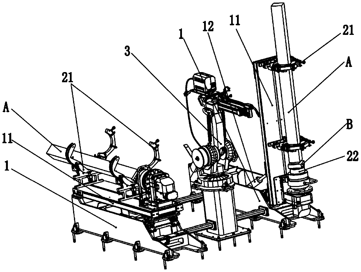
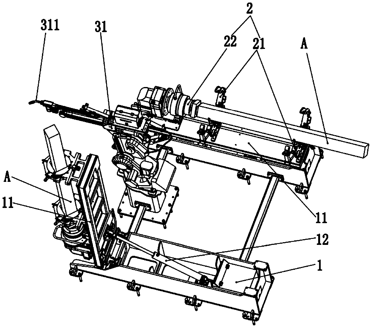
[0041] combine Figure 1 to Figure 2 , this embodiment provides an aluminum rod welding device, including a workbench 1 , a clamping mechanism 2 and a welding mechanism 3 .

[0042] There is a rotatable base 11 on the workbench 1, and the base 11 rotates from a horizontal state to a vertical state, so as to perform welding work accordingly. Wherein, when the base 11 is in a horizontal state, it is placed relatively laterally on the workbench 1 , at this time, the operator can perform loading and unloading. The aluminum rod A and the welding block B are respectively clamped and fixed on the clamping mechanism 2 before the material loading is welded. After blanking is welding, the welded aluminum rod A and welding block B are taken out from the clamping mechanism 2 . When the base 11 is in a vertical state, it is vertically perpendicular to the workbench 1, and the welding mechanism 3 performs welding work at this time. In this embodiment, one end of the base 11 is hingedly a...

Embodiment 2

[0053] The present application further provides an aluminum rod welding method, using the above-mentioned aluminum rod welding device to weld the aluminum rod A and the welding block B, including the following steps:

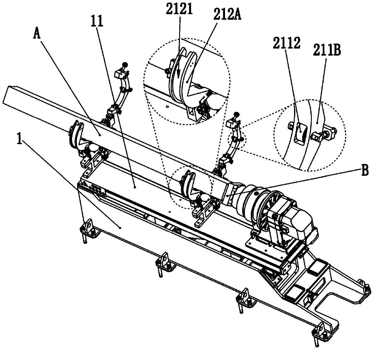
[0054] S1: The base 11 is in a horizontal state, fix the aluminum rod A to be welded on the first clamping part 21, and fix the welding block B on the second clamping part 22, so that the aluminum rod A and the welding block B are mutually abut and be at the same level.

[0055] Specifically, during the feeding process, the base 11 is placed laterally on the workbench 1, the aluminum rod A is placed in the accommodating cavity 212C of the limit seat 212 of the first clamping member 21, and the position of the limit seat 212 is locked. The two arc-shaped parts 212A lock and fix the opening and closing part 211B of the support base 211 and the seat part 211A, so that the limiting base 212 is accommodated in the cavity 211C to rotate relative to the support base 21...


PUM


Abstract

The invention provides an aluminum rod welding device, and relates to the technical field of welding. The aluminum rod welding device includes a working table, a clamping mechanism and a welding mechanism, the working table is provided with a rotatable base, the base rotates from a transverse horizontal state to a longitudinal vertical state, the clamping mechanism includes a first clamping pieceand a second clamping piece which are successively arranged in the horizontal direction of the base, a to-be-welded aluminum rod is clamped and fixed to the first clamping piece in the horizontal direction, a welding block to be welded to the aluminum rod is clamped and fixed to the second clamping piece, and the welding mechanism includes a high-frequency induction welder and an induction heater.The working table is provided with the rotatable base, when the base is in a horizontally and transversely placed state, feeding and discharging are conducted, thus a to-be-welded area corresponds tothe welding mechanism, after welding, the base rotates to the initial transverse horizontal state and then discharging is conducted, operation is easy and convenient, both time and labor are saved, automated mass welding work is facilitated, and high-efficiency and normal operation of the welding work is ensured. The invention further provides an aluminum rod welding method.

Description

technical field [0001] The invention relates to the field of welding technology, in particular to an aluminum rod welding device and a welding method thereof. Background technique [0002] At present, for the welding of aluminum rods with wide applicability, the method of direct welding after clamping and fixing is generally adopted. For example, Chinese patent CN104874902A discloses a welding method for fork-shaped aluminum pipe fittings, which adopts bracket tooling for positioning, and welding is performed after the support is fixed, so as to eliminate the unfused defect of the weld seam on the back of the fork-shaped aluminum pipe fittings. Although it can meet the welding requirements of most processes, the direct welding work on the clamped and fixed workbench cannot effectively avoid the operator of loading and unloading, and in order not to affect the normal operation of other processes, avoidance design is required, which is time-consuming Laborious and welding eff...

Claims


Application Information

Patent Timeline
Patent Type & Authority Applications(China)
IPC IPC(8): B23K13/01B23K37/04B23K37/02
CPCB23K13/01B23K37/0443B23K37/0252
Inventor 陈雄辉王新华戴沪华谢传禄宋荔城卓长青唐金平
Owner XIAMEN AEROSPACE SIERT ROBOT SYST CO LTD
Why Eureka
Try Eureka