Automatic clamping sling for engine cover

An engine cover and automatic clamping technology, applied in the field of EMS conveying system, can solve the problems of unobstructed passage, occupying ground logistics passage and material rack storage area, and crowded process area, so as to improve the automation rate and meet the needs of high-paced production. , the effect of saving floor space

Pending Publication Date: 2020-02-07
SHANGHAI FULANGDE MACHINERY EQUIP
View PDF0 Cites 0 Cited by
  • Summary
  • Abstract
  • Description
  • Claims
  • Application Information

AI Technical Summary

Problems solved by technology

[0002] At present, in the automobile body production workshop, the transportation of the engine cover subassembly and welding station to the surface adjustment line is in the form of artificial logistics racks on the ground. During the transportation process, a large number of artificial logistics vehicles are used to frequently dump materials, occupying a large amount of ground. The logistics channel and rack storage area cause congestion in the process areas on the ground and the channel is not smooth

Method used


Image

  • Automatic clamping sling for engine cover
  • Automatic clamping sling for engine cover
  • Automatic clamping sling for engine cover

Examples


Embodiment

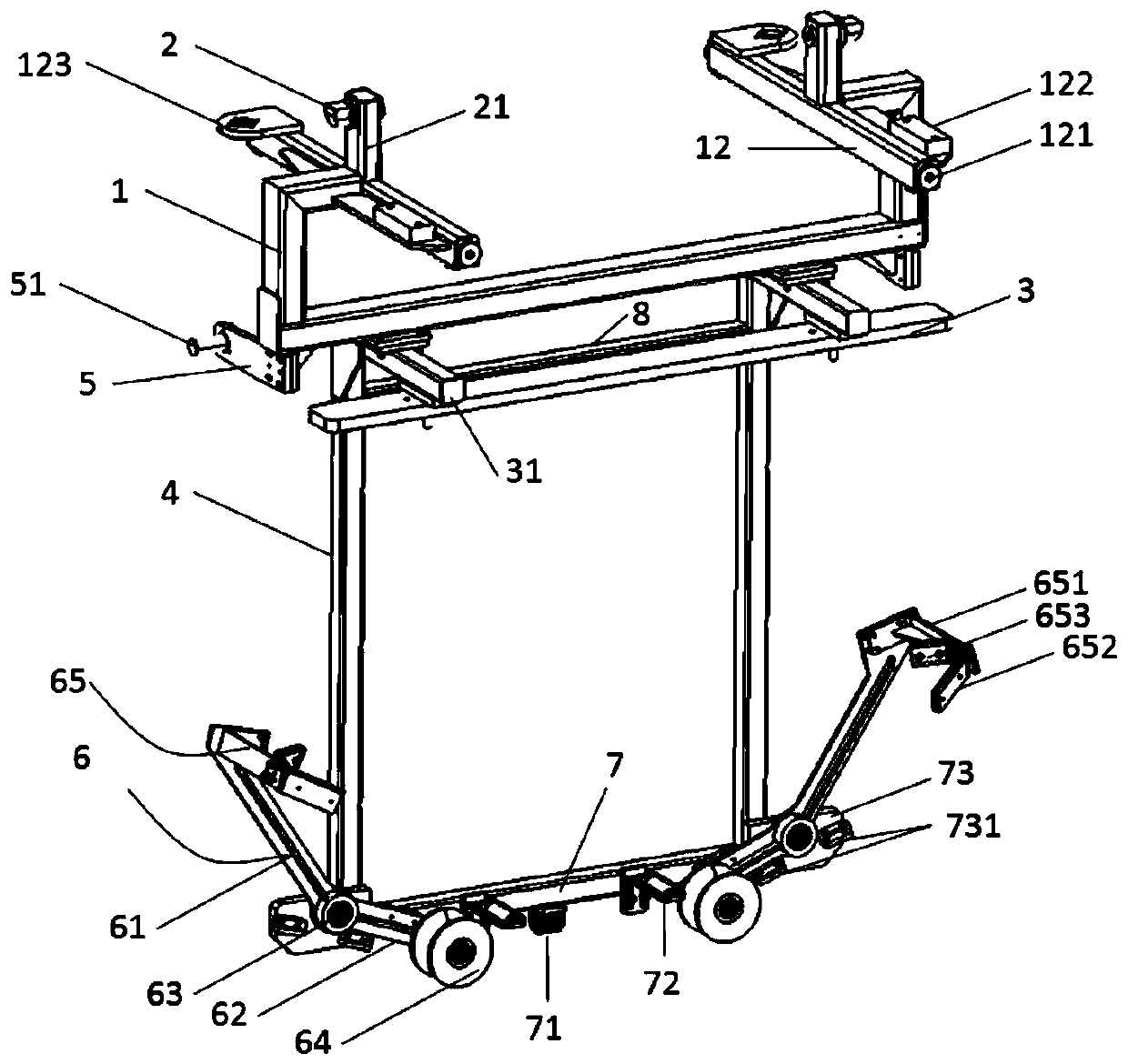
[0031] An engine cover automatic clamping spreader, such as figure 1 , the spreader includes a positioning mechanism, a bracket mechanism and a plurality of lever mechanisms 6, the positioning mechanism is fixed above the bracket mechanism, the lever mechanism 6 includes a guide rod 61, a connecting rod 62, a rotating wheel 63 and a supporting wheel 64, and the rotating wheel 63 is rotatably connected with the bottom angle of the bracket mechanism. The guide rod 61 is fixed on the end of the rotating wheel 63 away from the bracket mechanism. The connecting rod 62 is fixed on the end of the rotating wheel 63 close to the bracket mechanism. The support member 65 on the edge of the engine cover, the other end of the connecting rod 62 is provided with a supporting wheel 64 that carries the bottom of the engine cover. The wheel 64 and the support member 65 abut against the bottom and the edge of the engine cover respectively, and are in a clamped state.

[0032] The support member...


PUM


Abstract

The invention relates to an automatic clamping sling for an engine cover. The automatic clamping sling for the engine cover comprises a positioning mechanism, a bracket mechanism and a plurality of lever mechanisms (6), wherein the positioning mechanism is fixedly arranged above the bracket mechanism. Each lever mechanism (6) comprises a guide rod (61), a connecting rod (62), a rotating wheel (63)and a riding wheel (64), wherein the rotating wheel (63) is rotationally connected with the bottom corner of the bracket mechanism, the guide rod (61) is fixedly arranged at one end, far away from the bracket mechanism, of the rotating wheel (63), the connecting rod (62) is fixedly arranged at one end, close to the bracket mechanism, of the rotating wheel (63), the other end of the guide rod (61)is provided with a supporting part (65) for bearing the edge of the engine cover, and the other end of the connecting rod (62) is provided with the riding wheel (64) for bearing the bottom of the engine cover. Compared with the prior art, the automatic clamping sling for the engine cover has the advantages of being simple and reasonable in structure, ingenious in design, capable of automaticallyclamping and releasing parts by utilizing lever swing arms and the gravity of the engine cover and the like.

Description

technical field [0001] The invention relates to the field of EMS delivery systems, in particular to an engine cover automatic clamping hanger. Background technique [0002] At present, in the automobile body production workshop, the transportation of the engine cover subassembly and welding station to the surface adjustment line is in the form of artificial logistics racks on the ground. During the transportation process, a large number of artificial logistics vehicles are used to frequently dump materials, occupying a large amount of ground. The logistics channel and rack storage area cause congestion in the process areas on the ground and the channel is not smooth. [0003] In view of the current status of the ground transportation of the engine cover in the automotive industry, the pioneering use of the aerial EMS spreader transportation system saves ground space, reduces human resources, improves automation, and meets the needs of high-tempo production. Contents of the...

Claims


Application Information

Patent Timeline
Patent Type & Authority Applications(China)
IPC IPC(8): B62D65/18
CPCB62D65/18
Inventor 张留阳
Owner SHANGHAI FULANGDE MACHINERY EQUIP
Why Eureka
Try Eureka