
Stacking and transferring system for shaft products

A technology for products and shafts, which is applied in the field of stacking and transfer systems for shaft products, can solve the problems of circumferential rotation error, difficulty in achieving circumferential clamping and positioning, and large space occupation of storage areas, so as to prevent circumferential rotation and improve Efficiency and precision, the effect of meeting the requirements of transshipment

Active Publication Date: 2020-02-07
CHONGQING UNIV
View PDF12 Cites 9 Cited by
  • Summary
  • Abstract
  • Description
  • Claims
  • Application Information

AI Technical Summary

Problems solved by technology

[0004] Due to the smooth outer peripheral surface of shaft products, it is difficult to achieve circumferential clamping and positioning
The existing clamping bases for shafts generally use arc-shaped grooves or V-shaped grooves to directly support shaft products, but when shaft products are transported between different stations, there will inevitably be circumferential rotation errors, resulting in The positioning references of each station are different, which not only needs to be repositioned and fixed, which reduces efficiency, but also there will inevitably be positioning errors in multiple positionings, which will lead to problems related to the processing of shaft products and the installation of parts inside shaft products. a certain position error
[0005] Due to the lack of accompanying fixtures, hoisting tools are generally used to hoist shaft products to the storage area at present, but the hoisting mechanism cannot meet the stacking requirements of the three-dimensional warehouse for shaft products, resulting in a large space occupation in the storage area, and there are still damaged shafts during the hoisting process safety risks such as

Method used


Image

  • Stacking and transferring system for shaft products
  • Stacking and transferring system for shaft products
  • Stacking and transferring system for shaft products

Examples


Embodiment Construction

[0046] The present invention will be further described below in conjunction with the accompanying drawings and specific embodiments, so that those skilled in the art can better understand the present invention and implement it, but the examples given are not intended to limit the present invention.

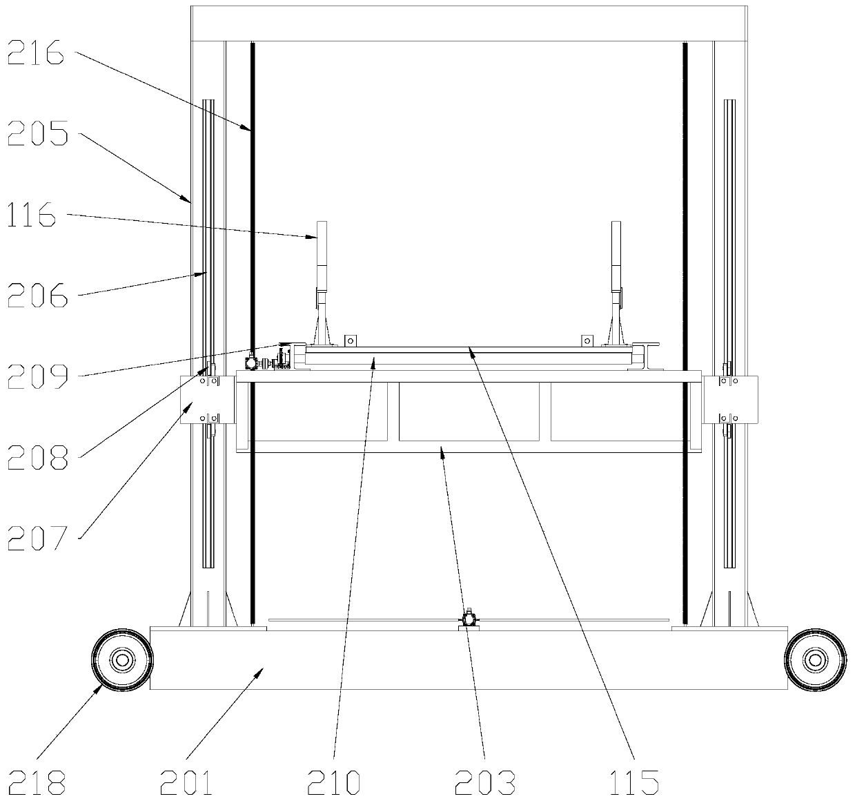
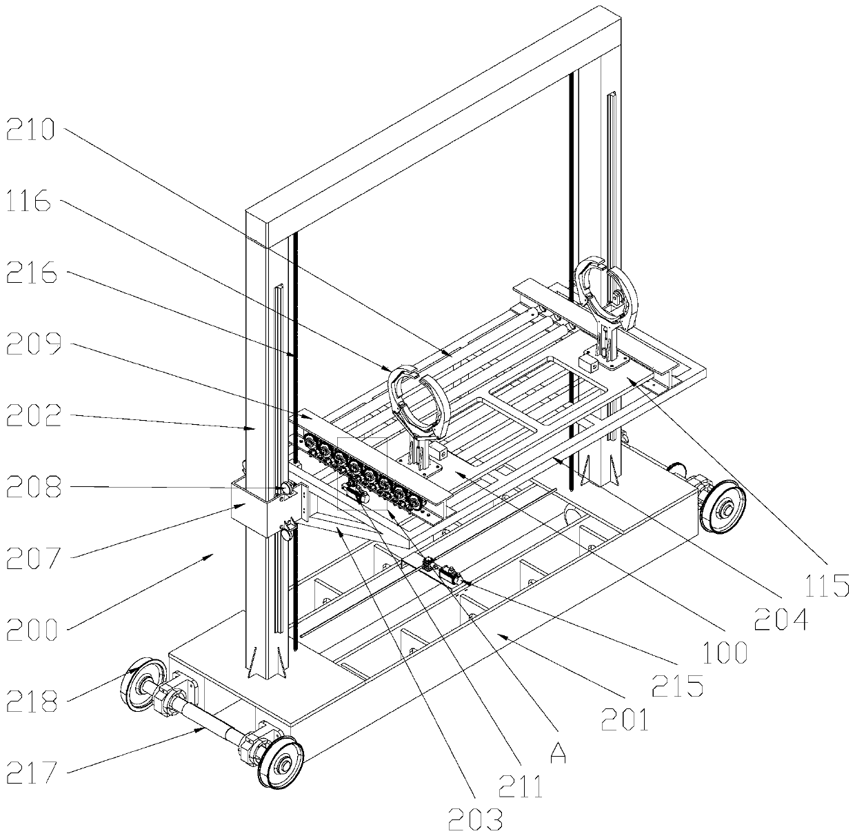
[0047] Such as figure 1 Shown is a schematic structural view of an embodiment of the shaft product stacking and transferring system of the present invention. The stacking and transfer system for shaft products in this embodiment includes a stacker 200 and a pallet 100 .

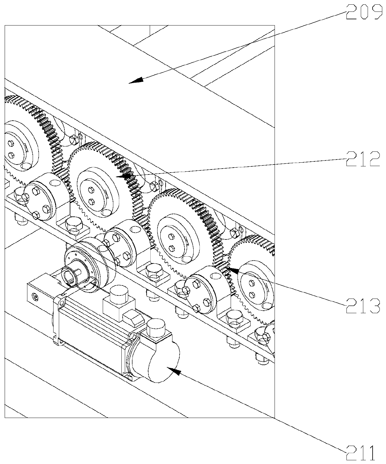
[0048] The stacker of the present embodiment includes a chassis 201, on which a vertical slide rail 202 is provided, on which a lifting frame 203 slidingly fitted is provided on the vertical sliding rail 202, and on the lifting frame 203 is provided with a structure for transporting the accompanying fixture 100 to A warehouse or transport mechanism 204 that receives pallets 100 from a warehouse. The lifting frame...


PUM


Abstract

The invention discloses a stacking and transferring system for shaft products. The stacking and transferring system for the shaft products comprises a stacker and a following clamp; the stacker comprises a base plate, and vertical sliding rails are arranged on the base plate; a lifting frame in sliding fit with the vertical sliding rails is arranged on the vertical sliding rails; a conveying mechanism for conveying the following clamp to a warehouse or receiving the following clamp from the warehouse is arranged on the lifting frame; the following clamp comprises a following base; at least twoclamp units used for clamping the shaft products are arranged on the following base at intervals; each clamp unit comprises a holding tool base; two ends of each holding tool base are respectively provided with holding arms which are rotationally matched with the holding tool base; each holding tool base is provided with a holding driving mechanism used for driving the holding arms to rotate andholding or loosening the shaft products; and the holding tool bases and the holding arms are respectively provided with arc-shaped grooves or V-shaped grooves matched with the shaft products. The stacking and transferring system for the shaft products can meet the stacking and transferring requirements of the shaft products.

Description

technical field [0001] The invention relates to a stacker, in particular to a stacking and transporting system for shaft products. Background technique [0002] The stacker is the most important lifting and transportation equipment in the three-dimensional warehouse, and it is a symbol representing the characteristics of the three-dimensional warehouse. The main function of the stacking crane is to run back and forth in the aisle of the three-dimensional warehouse, store the goods at the entrance of the aisle into the compartment of the shelf, or take out the goods in the compartment and transport them to the entrance of the aisle. For shaft products, since they cannot be positioned in the circumferential direction, they are prone to rolling after being stored in the three-dimensional warehouse, that is, the shaft products are not convenient for storage in the three-dimensional warehouse. [0003] The accompanying fixture is a machine tool fixture that is automatically move...

Claims


Application Information

Patent Timeline
IPC IPC(8): B65G1/04B65G47/90
CPCB65G1/0407B65G47/90B65G2201/0217
Inventor 杨波刘子晖王时龙康玲陈俊明
Owner CHONGQING UNIV
Learn More