Parameter wavelet threshold signal denoising method based on improved artificial bee colony algorithm

An artificial bee colony algorithm and wavelet threshold technology, applied in computing, artificial life, computing models, etc., can solve problems such as low convergence accuracy, easy to fall into local optimum, and slow convergence speed

Active Publication Date: 2020-02-07
QINGDAO UNIV OF SCI & TECH +2
View PDF5 Cites 8 Cited by
  • Summary
  • Abstract
  • Description
  • Claims
  • Application Information

AI Technical Summary

Problems solved by technology

However, these methods have problems such as slow convergence spe

Method used


Image

  • Parameter wavelet threshold signal denoising method based on improved artificial bee colony algorithm
  • Parameter wavelet threshold signal denoising method based on improved artificial bee colony algorithm
  • Parameter wavelet threshold signal denoising method based on improved artificial bee colony algorithm

Examples


Embodiment 1

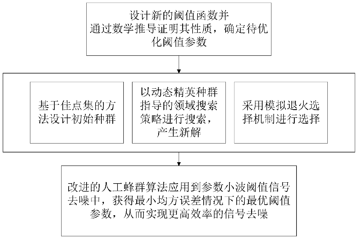
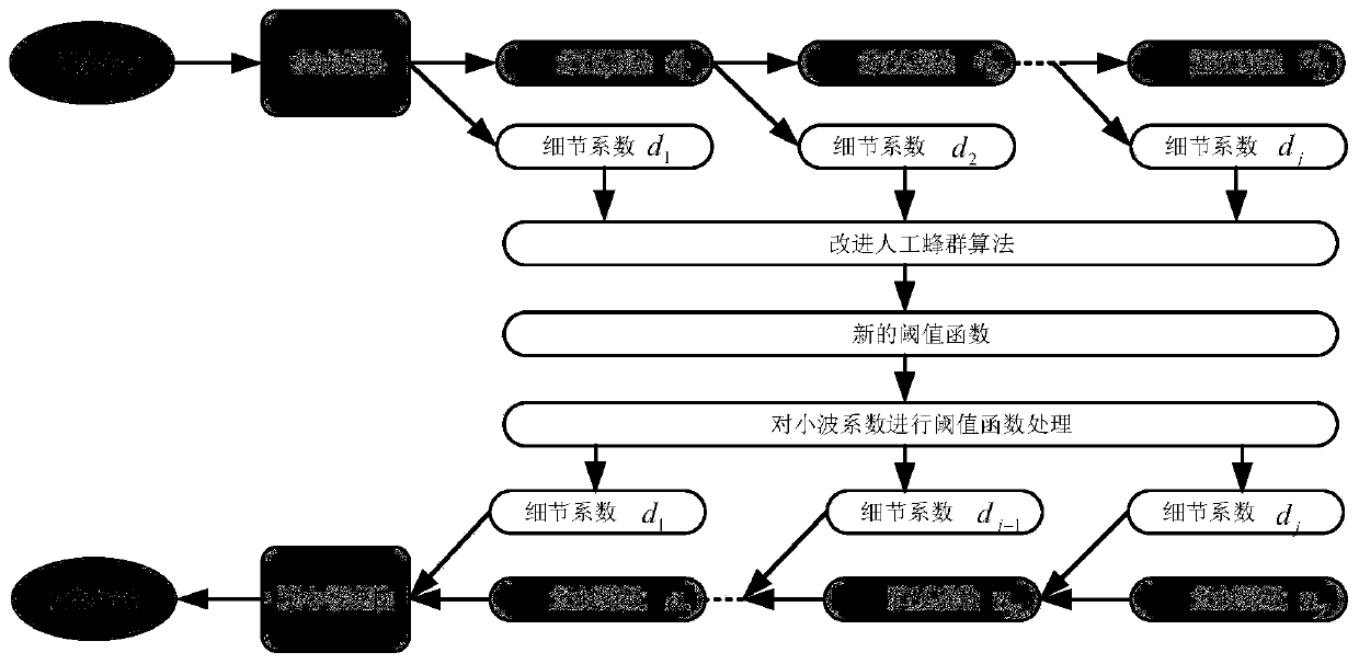
[0073] see figure 1 , 2 As shown, a kind of parametric wavelet threshold signal denoising method based on the improved artificial bee colony algorithm described in this embodiment includes the following steps:

[0074] S1: Design a new threshold function based on the traditional threshold function, prove its properties through mathematical derivation, and determine the threshold parameters to be optimized; the specific steps are as follows:

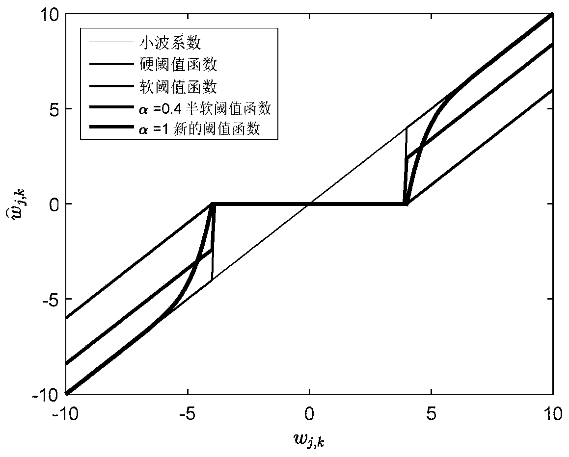
[0075] S1-1. A new threshold function construction:

[0076] The threshold function embodies different processing strategies and different estimation methods for wavelet coefficients, which directly affects the final denoising effect. A reasonable threshold function needs to meet the continuous input-output curve, relatively smooth processing, and keep the wavelet coefficient of the signal basically unchanged. Therefore, the present invention proposes a new improved threshold function for soft and hard threshold functions and semi-soft...

Embodiment 2

[0124] In order to verify the effectiveness of the improved artificial bee colony algorithm, the performance of the improved artificial bee colony algorithm and the original ABC, ECABC, original PSO, MPSO algorithms was analyzed. The computer configuration used is: Intel i5-4570 processor, Windows 7 operating system, 4G memory, MATLAB R2015b. Select the six benchmark functions shown in Table 1 to test the performance of the algorithm. where Sphere(f 1 ) function is a continuous unimodal function, Step(f 2 ) function is a discontinuous step unimodal function, Rastrigin(f 3 ), Ackley (f 4 ), Schwefel 2.26(f 5 ) function is a continuous multimodal function, RosenBrock(f 6 ) function is a unimodal function when D≤3, and a multimodal function when D>3. The optimal value of the five functions is 0, and the acceptable value is 1×10 -8 , acceptable values ​​represent satisfactory solutions of the function.

[0125] Table 1 Benchmark function

[0126]


PUM


Abstract

The invention discloses a parameter wavelet threshold signal denoising method based on an improved artificial bee colony algorithm. The parameter wavelet threshold signal denoising method comprises the steps: firstly obtaining a to-be-denoised signal, carrying out wavelet transformation, and obtaining a wavelet coefficient; designing a new threshold function on the basis of a traditional thresholdfunction, proving the property of the new threshold function through mathematical derivation, and determining threshold parameters to be optimized; improving an original artificial bee colony algorithm; taking a mean square error between the to-be-denoised signal and the denoised signal as a fitness function of the improved artificial bee colony algorithm in S3, and obtaining an optimal thresholdparameter under the condition of obtaining a minimum mean square error; and applying the optimal threshold parameter obtained in the step S4 to the new threshold function in the step S2, performing shrinkage processing on the wavelet coefficient to obtain a new wavelet coefficient, and performing inverse wavelet transform to obtain a denoised signal. According to the parameter wavelet threshold signal denoising method, a smaller mean square error, a higher output signal-to-noise ratio and a larger noise rejection ratio can be obtained.

Description

technical field [0001] The invention belongs to the field of wavelet threshold value signal denoising, and in particular relates to a parametric wavelet threshold signal denoising method based on an improved artificial bee colony algorithm. Background technique [0002] Signals are often polluted by noise in the process of acquisition, transmission and processing, which will lead to the degradation of signal quality. The wavelet threshold denoising method can obtain the asymptotically optimal estimation of the original signal, and has been most widely used. The denoising performance of common wavelet threshold denoising methods depends on the accurate estimation of noise variance; however, in practical applications, it is difficult to know the exact noise variance. Another factor that determines the denoising performance of the wavelet threshold denoising method is the threshold function. The common threshold functions include hard threshold function, soft threshold functio...

Claims


Application Information

Patent Timeline
IPC IPC(8): G06K9/00G06N3/00
CPCG06N3/006G06F2218/06
Inventor 王景景李嘉恒杨星海施威郭瑛张天遨王綝郑欣杨清
Owner QINGDAO UNIV OF SCI & TECH
Why Eureka
Try Eureka