Lens type ultra-wide spectrum electromagnetic pulse radiating antenna and antenna array

An electromagnetic pulse and radiating antenna technology, which is applied in the antenna, radiating element structure, circuit, etc., can solve the problems of no spatial focusing ability and low main axis radiation field strength, and achieve improved forward radiation ability, compact structure, and reduced The effect of lateral radiation

Active Publication Date: 2020-02-07
NORTHWEST INST OF NUCLEAR TECH
View PDF9 Cites 5 Cited by
  • Summary
  • Abstract
  • Description
  • Claims
  • Application Information

AI Technical Summary

Problems solved by technology

Since the TEM horn antenna radiates spherical waves and has no spatial focusing capability, the main axis radiation field strength is low

Method used


Image

  • Lens type ultra-wide spectrum electromagnetic pulse radiating antenna and antenna array
  • Lens type ultra-wide spectrum electromagnetic pulse radiating antenna and antenna array
  • Lens type ultra-wide spectrum electromagnetic pulse radiating antenna and antenna array

Examples


Embodiment 1

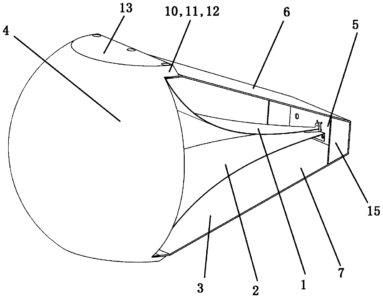
[0042] Such as Figure 1 to Figure 4 As shown, a lens-type ultra-broadband electromagnetic pulse radiation antenna includes an upper plate 1, a lower plate 2, a housing 3, a lens 4 and a cable head (not shown in the figure);

[0043] The upper plate 1 and the lower plate 2 form a TEM horn with gradually changing impedance,

[0044] The shell 3 includes a bottom plate 5, an upper side plate 6 and a lower side plate 7;

[0045] Both the starting ends of the upper pole plate 1 and the lower pole plate 2 are connected to the bottom plate 5, and the starting ends of the upper pole plate 1 are connected to the core wire of the cable head;

[0046] One end of the upper side plate 6 is connected to the upper edge of the bottom plate 5, and the lower surface of the other end is connected to the aperture end of the upper pole plate 1;

[0047] One end of the lower side plate 7 is connected to the lower edge of the bottom plate 5, and the upper surface of the other end is connected to ...

Embodiment 2

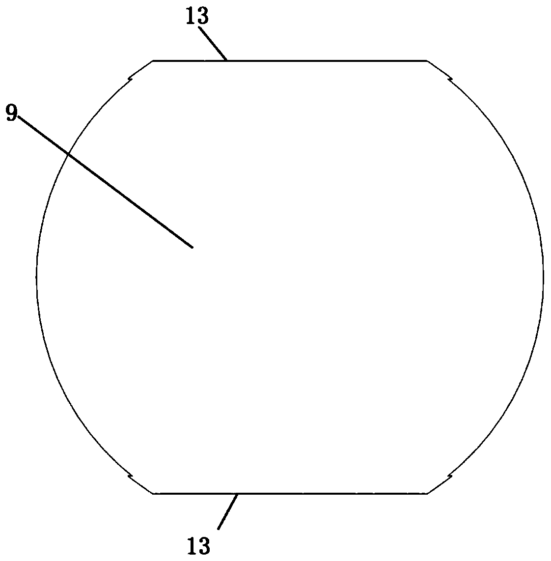
[0057] Such as Figure 5 As shown, the present invention also provides embodiment 2, and the structure of embodiment 2 is basically the same as embodiment 1, and the only difference is:

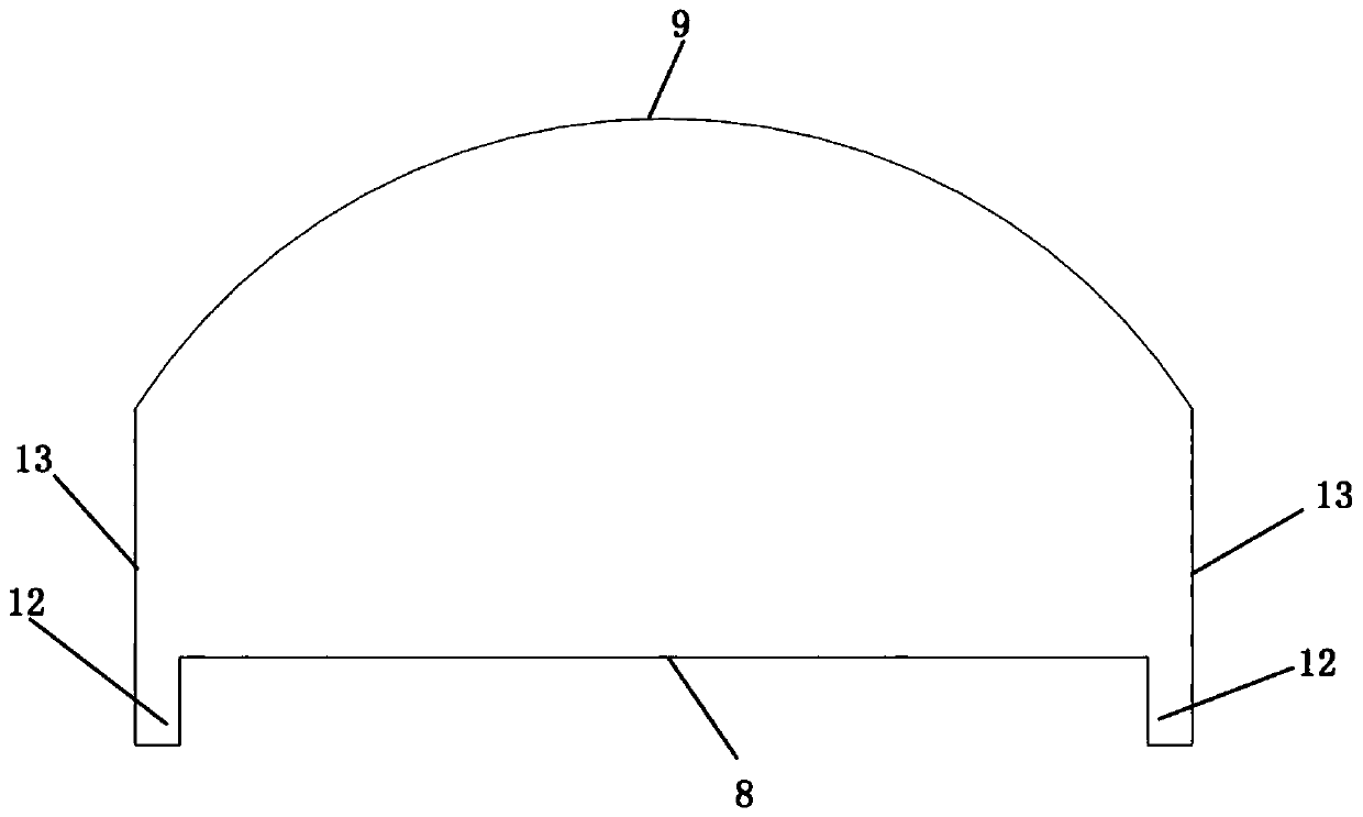
[0058] The periphery of the lens 4 in Embodiment 2 is cut with two first planes 13 parallel to each other and two second planes 14 parallel to each other; the first plane 13 and the second plane 14 are perpendicular to each other, and its purpose is to further enhance the The space utilization rate when the single antenna structure forms an antenna array.

[0059] In addition, on the basis of Embodiment 1 and Embodiment 2, the present invention has also made the following structural optimizations:

[0060] 1. The casing 3 also includes two trapezoidal side plates 16; the two trapezoidal side plates 16 are respectively located on the left and right sides of the bottom plate 5; The two waists of the plate 16 are respectively connected to the side edge of the upper plate 1 and the side edge of...


PUM


Abstract

The invention discloses a lens type ultra-wide spectrum electromagnetic pulse radiating antenna and antenna array. The structure is simple, and a radiated field strength of a principal axis of a TEM horn antenna can be effectively improved. The antenna includes an upper pole plate and a lower pole plate; the upper pole plate and the lower pole plate form a TEM horn shape having a gradually-variedimpedance; the antenna further includes a housing, a lens and a cable head; the housing includes a bottom plate, an upper side plate and a lower side plate; start ends of the upper pole plate and thelower pole plate are connected to the bottom plate, and the start end of the upper pole plate is connected to a core wire of the cable head; one end of the upper side plate is connected to an upper edge of the bottom plate, and a lower surface of the other end of the upper side plate is connected to an aperture end of the upper pole plate; one end of the lower side plate is connected to a lower edge of the bottom plate, and an upper surface of the other end of the lower side plate is connected to an aperture end of the lower pole plate; an inner surface of the lens is a plane; an outer surfaceof the lens is a spherical surface, an ellipsoidal surface or a double curved surface; and the inner surface of the lens is fixedly connected to one side, located on the aperture end, of each of theupper side plate and the lower side plate.

Description

technical field [0001] The invention belongs to the electromagnetic pulse measurement technology, and relates to an antenna, in particular to a lens-type ultra-wide-spectrum electromagnetic pulse radiation antenna and an antenna array. Background technique [0002] Ultra-broadband electromagnetic pulses usually refer to pulse fronts or pulse widths in sub-nanoseconds (10 -10 s) Transient electromagnetic pulses with a magnitude and a spectrum range of tens of MHz to several GHz, which have broad spectrum and short pulse characteristics similar to nuclear electromagnetic pulses. It has been widely used in many fields such as target detection, target recognition, electromagnetic damage, electromagnetic compatibility, and biomedicine. [0003] The ultra-broadband electromagnetic pulse radiation antenna is the core component of the ultra-broadband microwave system, and its function is to radiate the ultra-broadband pulse generated by the pulse source to a designated area with a ...

Claims


Application Information

Patent Timeline
Patent Type & Authority Applications(China)
IPC IPC(8): H01Q1/36H01Q15/02H01Q13/02
CPCH01Q1/36H01Q15/02H01Q13/02
Inventor 易超龙樊亚军石一平乔汉青谢佳玲石磊朱郁丰夏文锋卢彦雷张兴家王翔宇方旭
Owner NORTHWEST INST OF NUCLEAR TECH
Why Eureka
Try Eureka