Double-coil coupling inductance type impedance source inverter for suppressing direct-current link voltage peak

A technology of coupled inductance and voltage spikes, applied in the direction of converting irreversible DC power input to AC power output, electrical components, output power conversion devices, etc., can solve problems such as breakdown of switching devices, avoid breakdown, ensure The effect of running stability and improving efficiency

Inactive Publication Date: 2020-02-07
NORTHEAST DIANLI UNIVERSITY
View PDF11 Cites 4 Cited by
  • Summary
  • Abstract
  • Description
  • Claims
  • Application Information

AI Technical Summary

Problems solved by technology

[0005] Aiming at the problem that the current double-coil coupled inductance type impedance source inverter has too high a DC link voltage peak and easily causes the breakdow

Method used


Image

  • Double-coil coupling inductance type impedance source inverter for suppressing direct-current link voltage peak
  • Double-coil coupling inductance type impedance source inverter for suppressing direct-current link voltage peak
  • Double-coil coupling inductance type impedance source inverter for suppressing direct-current link voltage peak

Examples


specific Embodiment approach 1

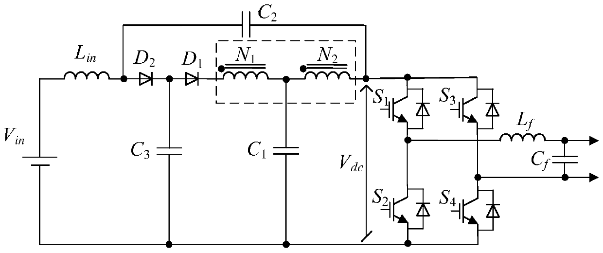
[0045] Specific implementation mode 1. Combination Figure 1 to Figure 3 As shown, the present invention provides a dual-coil coupled inductance-type impedance source inverter that suppresses DC link voltage spikes, including an inverter bridge circuit, a power supply circuit and a clamping circuit;

[0046] The power supply circuit includes a DC power supply V in , inductance L in , Diode D 1 , double-coil coupled inductance unit and capacitor C 1 ;

[0047] The clamping circuit consists of a capacitor C 2 , capacitance C 3 and diode D 2 ;

[0048] DC power V in The positive connection of the inductance L in at one end, the inductance L in The other end of the diode is connected to D 2 anode of the diode D 2 The cathode connection capacitance C 3 One end of the capacitor C 3 Connect the other end of the DC power supply V in the negative pole;

[0049] The double-coil coupled inductor unit includes two coupled inductors connected in series, and the two ends and...

specific Embodiment 1

[0055] For the dual-coil coupled inductive impedance source inverter that suppresses the DC link voltage spike, combined with figure 1 As shown, the double-coil coupled inductance unit is further explained:

[0056] The double-coil coupled inductance unit includes a coupled inductance N 1 and coupled inductor N 2 ,

[0057] Coupled inductor N 1 The terminal of the same name as the first connection terminal, the coupled inductor N 1 The dissimilar terminal is connected to the coupled inductor N 2 The dotted end of the coupled inductor N 2 The opposite end of the terminal serves as the third connection terminal, the coupled inductor N 2 The end with the same name as the second connection end.

[0058] The inverter described in this embodiment is designed for the improved T-source inverter.

[0059] further, combine figure 1 As shown, the input voltage of the inverter bridge circuit V dc for:

[0060]

[0061] where K is the coupling inductance coefficient, d is t...

specific Embodiment 2

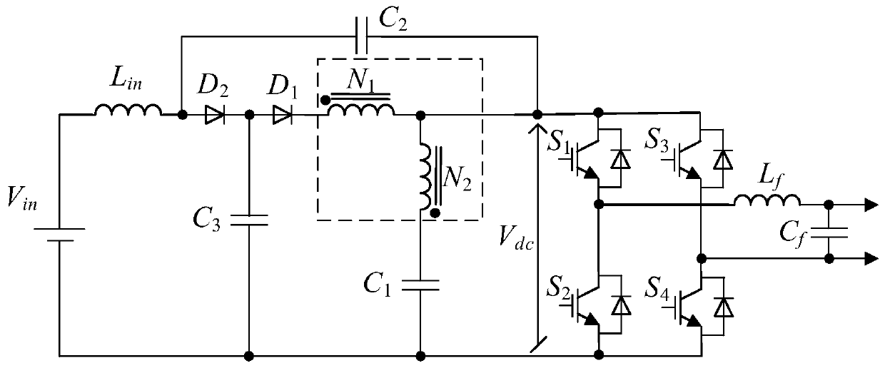
[0090] For the dual-coil coupled inductive impedance source inverter that suppresses the DC link voltage spike, combined with figure 2 As shown, the double-coil coupled inductance unit is further explained:

[0091] The double-coil coupled inductance unit includes a coupled inductance N 1 and coupled inductor N 2 , coupled inductance N 1 The terminal of the same name as the first connection terminal, the coupled inductor N 1 The dissimilar terminal is connected to the coupled inductor N 2 The opposite end of the coupled inductor N 1 The opposite end of the terminal serves as the third connection terminal, the coupled inductor N 2 The end with the same name as the second connection end.

[0092] The inverter described in this embodiment is designed for the existing LCCT type Z-source inverter.


PUM


Abstract

The invention discloses a double-coil coupling inductance type impedance source inverter for suppressing a direct-current link voltage peak, and belongs to the technical field of power electronics. The double-coil coupling inductance type impedance source inverter solves the problem that an existing double-coil coupling inductance type impedance source inverter is prone to causing breakdown of a switching device due to the fact that the voltage peak of a direct-current chain is too high. The inverter comprises an inverter bridge circuit, a power supply circuit and a clamping circuit, the powersupply circuit comprises a direct-current power supply Vin, an inductor Lin, a diode D1, a double-coil coupling inductor unit and a capacitor C1; the clamping circuit comprises a capacitor C2, a capacitor C3 and a diode D2; the inverter bridge circuit is used for supplying power to a power grid or a load. According to the invention, energy consumed on a switch tube in a voltage peak form can be recycled, and the efficiency of the inverter is further improved.

Description

technical field [0001] The invention relates to a dual-coil coupled inductance-type impedance source inverter capable of suppressing DC link voltage spikes, and belongs to the technical field of power electronics. Background technique [0002] Dual-coil coupled inductance impedance source inverters, such as T source inverters, LCCT type Z source inverters, and Γ source inverters, are new technologies suitable for photovoltaic power generation, wind power generation, and biomass power generation in the future. Ideal high step-up ratio impedance source inverter for energy. However, the current dual-coil coupled inductance-type impedance source inverter generally has the problem of excessively high DC link voltage spikes. [0003] In the traditional design of the coupled inductance impedance source inverter, in order to deal with the breakdown of the switching tube caused by the high DC link voltage peak, switching devices with higher withstand voltage are often used. However...

Claims


Application Information

Patent Timeline
IPC IPC(8): H02M7/44H02M7/48H02M1/32
CPCH02M1/32H02M7/44H02M7/48H02M1/0038
Inventor 刘鸿鹏张书鑫张伟
Owner NORTHEAST DIANLI UNIVERSITY
Why Eureka
Try Eureka