Motor stator punching machining machine

A technology for motor stators and processing machinery, which is applied in the manufacture of stator/rotor bodies, etc. It can solve the problems of scrapped workpieces, offset of round steel plates, and offset of center punching grooves, etc., to reduce warpage or deformation, improve stability, The effect of guaranteeing accuracy

Active Publication Date: 2020-02-11
湖北宝达机电有限公司
View PDF6 Cites 9 Cited by
  • Summary
  • Abstract
  • Description
  • Claims
  • Application Information

AI Technical Summary

Problems solved by technology

[0003] 1. Due to manual operation, the center position of the processed round steel plate is easy to deviate, and the center of the processed round steel plate and the center of the stamping head are not in a state of direct opposition, which makes it easy to cause the center punching groove to deviate. At the same time, the round steel plate is also easy to The offset phenomenon occurs under the action of the stamping force, which affects the precision of the stamping process of the motor stator, and then affects the working efficiency and service life of the motor;
[0004] 2. There are many working grooves to be processed on the motor stator punching sheet, and the working grooves are close to the edge of the processed round steel plate. During the stamping process, the edge of the round steel plate is prone to upward warping. For thinner round steel plates, it is also necessary to There are serious problems such as distortion and deformation at the edge, which directly have a great impact on the quality of the stator punching of the motor, and even lead to the scrapping of the processed parts

Method used


Image

  • Motor stator punching machining machine
  • Motor stator punching machining machine
  • Motor stator punching machining machine

Examples


Embodiment Construction

[0028] The embodiments of the present invention will be described in detail below with reference to the accompanying drawings, but the present invention can be implemented in many different ways as defined and covered by the claims.

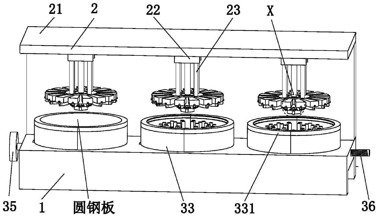
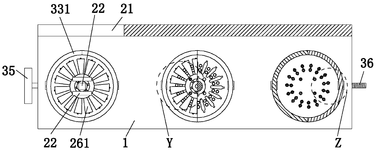
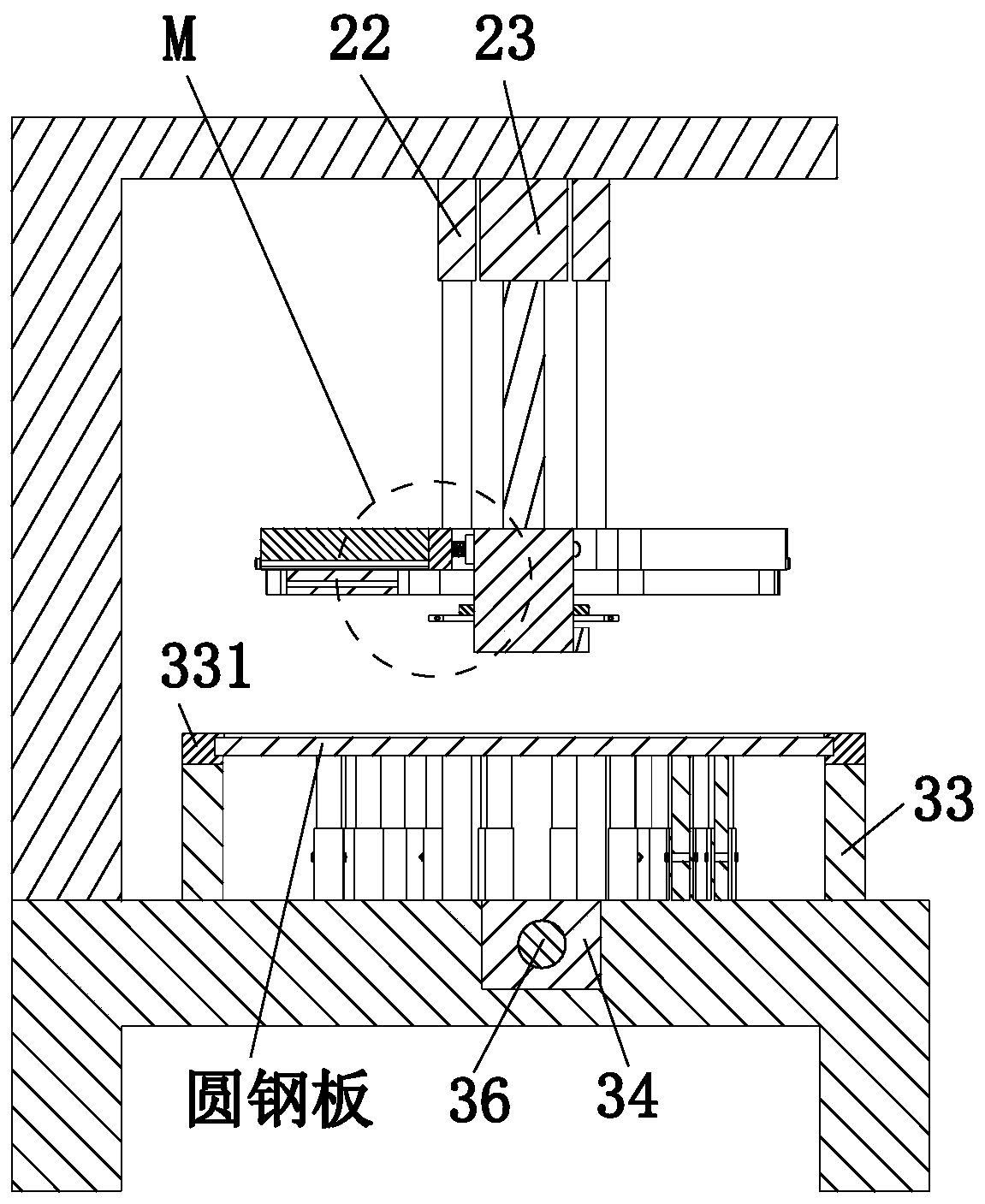
[0029] Such as Figure 1 to Figure 7 As shown, a motor stator stamping processing machine includes a workbench 1, a stamping device 2 and a clamping device 3, the upper end of the workbench 1 is equipped with a stamping device 2, and the lower part of the stamping device 2 is provided with a clamping device 3. The clamping device 3 is connected to the workbench 1 by sliding fit, and the clamping devices 3 are arranged equidistantly from left to right.

[0030]The stamping device 2 includes an inverted L-shaped frame 21, a No. 1 cylinder 22, a No. 2 cylinder 23, a stamping round block 24, a round seat plate 25 and a punching edge group 26, and the inverted L-shaped frame 21 is installed on the upper end surface of the workbench 1 The rear end of ...


PUM


Abstract

The invention relates to a motor stator punching machining machine. The machine comprises a workbench, a punching device and clamping devices, wherein the punching device is mounted at the upper end of the workbench, the clamping devices are arranged below the punching device, the clamping devices are connected with the workbench in a slide fit mode, and the clamping devices is arranged at equal distance from left to right. According to the motor stator punching machining machine, a multi-stage adjustable design concept is adopted for motor stator punching machining, the stability degree of round steel plate machining is improved, the accuracy of punching points is guaranteed, then the precision of the motor stator punching machining is improved, and meanwhile, a motor stator with the required number of slots can be machined according to requirements due to the fact that spacing of edge punching blocks and stretching and retracting of a second jacking support column are both controllable.

Description

technical field [0001] The invention relates to the field of motor stator punching equipment, in particular to a motor stator punching processing machine. Background technique [0002] The stator of the motor is the static part of the motor, and is an important part of the motor such as the generator and the starter. The stator is composed of three parts: the stator core, the stator winding and the frame. The main function of the stator is to generate a rotating magnetic field, while the rotor's The main function is to generate current by being cut by the magnetic force lines in the rotating magnetic field. According to the production process type, it can be divided into winding stator, three-piece stator, and whole-piece stator. According to the motor work type, it can be divided into synchronous motor stator and asynchronous motor stator. Motor stator The material and the accuracy of its processing have a direct impact on the energy consumption, work efficiency, noise and ...

Claims


Application Information

Patent Timeline
Patent Type & Authority Applications(China)
IPC IPC(8): B21D28/14B21D28/04B21D28/22H02K15/02
CPCB21D28/04B21D28/14B21D28/22H02K15/02
Inventor 王飞翔李海波
Owner 湖北宝达机电有限公司
Why Eureka
Try Eureka