Laser cutting mechanism

A laser cutting and loading technology, applied in the field of laser applications, can solve problems such as affecting cutting quality and inclination

Inactive Publication Date: 2020-02-11
东莞市史雷帝三维数控科技有限公司
0 Cites 2 Cited by

AI-Extracted Technical Summary

Problems solved by technology

[0003] like figure 1 The main body of product 4 is composed of plates with two downward notches. Sometimes, product 4 needs to be cut from it, so a cutting device is needed, usually a laser cutting device is used. Due to the Thickness problem, when laser cuttin...

Method used

First product 4 is placed on loading device 3, then according to the thickness of product 4 plates, drive cutting lifting block 10 to carry out lifting by cutting lifting cylinder 9, in lifting process, cutting lifting ball 17 and contact induction screen all the time 16 maintains a tangential state, so it can ensure that the cutting lifting block 10 moves up and down smoothly, ensures the verticality of the laser cutting head, and then ensures a good cutting effect, and at the same time will not cause excessive contact between the cutting lifting block 10 and the touch sensor screen 16. At the same time, it can also reflect the height of the elder brother’s cutting and lifting ball according to the induction signal on the touch-sensitive screen 16, which plays a role in verifying the lifting height. It can als...

Abstract

The invention relates to a laser cutting mechanism. The laser cutting mechanism comprises a lower frame and an upper frame. The lower frame is provided with bearing devices matched with a product. Theupper frame is provided with a laser cutting device. The laser cutting device comprises a cutting sleeve connected with the upper frame through connecting rods. The cutting sleeve is a cavity sleevewith an opening on the lower portion. The lower portion of the upper frame is provided with a cutting lifting cylinder of which the cylinder head penetrates into a cavity of the cutting sleeve. The lower portion of the cutting lifting cylinder is connected with a cutting lifting block. The lower portion of the cutting lifting block is connected with a laser cutter capable of feeding. The inner wall of the cutting sleeve is provided with a touch induction screen. Cutting lifting balls being tangential to and matched with the touch induction screen are embedded on the side face of the cutting lifting block. The laser cutting mechanism provided by the invention can ensure that a laser emitting head can keep in a vertical state all the time in the lifting process and then can ensure the good laser cutting effect.

Application Domain

Laser beam welding apparatus

Technology Topic

PhysicsEngineering +3

Image

  • Laser cutting mechanism
  • Laser cutting mechanism
  • Laser cutting mechanism

Examples

  • Experimental program(1)

Example Embodiment

[0018] In order to enable those skilled in the art to better understand the technical solutions of the present invention, the present invention will be described in detail below with reference to the accompanying drawings. The description in this section is only exemplary and explanatory and should not have any limitation on the scope of protection of the present invention. .
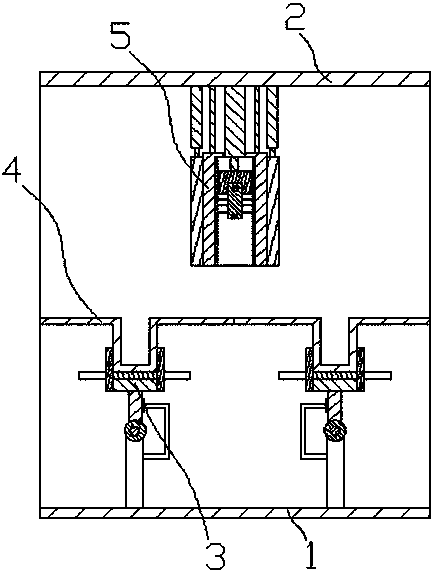
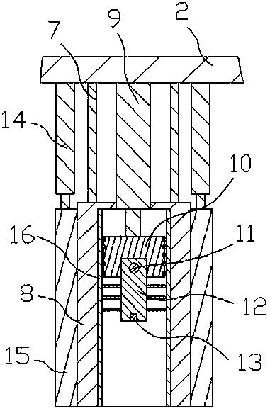
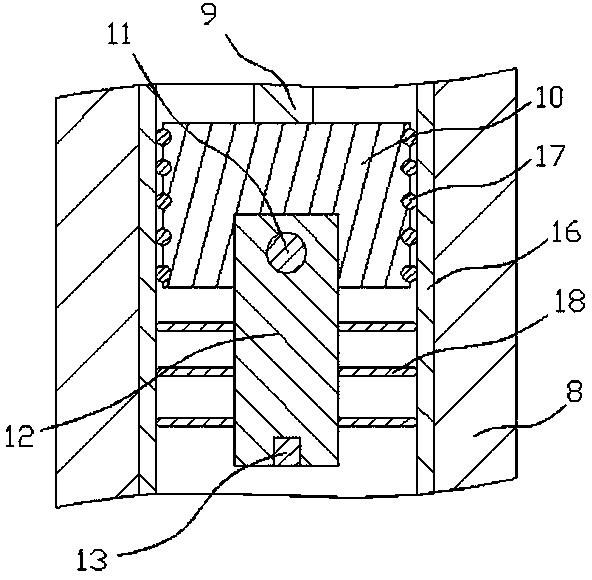
[0019] Such as Figure 1-3 As shown, the specific structure of the present invention is: a laser cutting mechanism, including a lower frame 1 and an upper frame 2. The lower frame 1 is provided with a material carrier 3 that matches the product 4, and the upper frame 2 A laser cutting device 5 is provided below. The laser cutting device 5 includes a cutting sleeve 8 connected to the upper frame 2 through a connecting rod 7. The cutting sleeve 8 is a cavity sleeve with a lower opening, and is provided below the upper frame 2. A cutting lift cylinder 9 with a cylinder head penetrated into the cavity of the cutting sleeve 8. A cutting lift block 10 is connected below the cutting lift cylinder 9 and a laser cutter capable of feeding is connected below the cutting lift block 10 The inner wall of the cutting sleeve 8 is provided with a touch-sensitive screen 16, and the side surface of the cutting lifting block 10 is embedded with a cutting lifting ball 17 tangentially matched with the touch-sensitive screen 16.
[0020] First place the product 4 on the loading device 3, and then according to the thickness of the plate of the product 4, the cutting lifting cylinder 9 is used to drive the cutting lifting block 10 up and down. During the lifting process, the cutting lifting ball 17 is always in phase with the touch sensing screen 16 Therefore, it can ensure that the cutting lifting block 10 is smoothly lifted and lowered, and the verticality of the laser cutting head is ensured, thereby ensuring a good cutting effect. At the same time, it will not cause wear due to excessive contact between the cutting lifting block 10 and the touch-sensitive screen 16, and It can also reflect the height of the elder brother's cutting lifting balls according to the induction signal on the touch sensor screen 16, which can verify the lifting height. It can also analyze whether there is a height difference between the cutting lifting balls of the same height on different sides to further ensure the smooth lifting The image produced by the touch-sensitive screen 16 can be directly transmitted to a computer for manual analysis, or can be automatically analyzed by a program set in the computer.
[0021] Such as image 3 As shown, the laser cutter includes a feed slot opened below the cutting lift block 10, and a cutting feed screw 11 and a cutting feed motor are provided in the feed slot. The cutting feed screw 11 11 The laser cutter body 12 is sleeved and fitted, and a laser emitting head 13 is arranged below the laser cutter body 12, and a cutting feed is arranged outside the lower part of the laser cutter body 12 beyond the cutting lift block 10 The limit rod 18, the outer end of the cutting feed limit rod 18 is arc-shaped, and is tangentially matched with the touch sensing screen 16.
[0022] The work of the laser cutter is as follows. First, it is started by the startup program in the main body 12 of the laser cutter, and then the laser emitting head 13 emits a vertical downward laser beam, and then the cutting and feeding screw 11 is driven to rotate by the cutting and feeding motor. In turn, the laser cutter body 12 is driven to feed, and the laser beam is fed, so as to realize the cutting of the product 4. During the feeding process of the laser cutter body 12, the cutting feed limit rod 18 is always in contact with the touch sensor screen. Cutting, in turn, can avoid the deviation of the laser cutter body 12, and further ensure the quality of the cutting. At the same time, the cutting feed limit rod 18 can also play a role in feedback of the height position.
[0023] Such as figure 2 As shown, the outer side of the cutting sleeve 8 is sleeved with a stopper lifting sleeve 15, and the upper part of the stopper lifting sleeve 15 is connected with a stopper lifting cylinder 14 arranged vertically below the upper frame 2. The stopper lifting sleeve 15 is an elastically deformable sleeve body, and is sealed and matched with the cutting sleeve 8.
[0024] The design of the stopper lifting cylinder 14 and the stopper lifting sleeve 15 can be brought into contact with the product 4 by the lowering of the stopper lifting sleeve 15, thereby forming a sealed laser cutting space. When cutting in a dusty space, it can be used Good protection, avoid dust from interfering with cutting.
[0025] Such as figure 2 As shown, the lower part of the side of the stopper lifting sleeve 15 is provided with a communication port, and an air pump is connected to the outside of the communication port, and the air pump is connected to a dust collection box or an oxygen tank.
[0026] The connecting port is opened and the air pump is connected. In the dust space, the dust can be sucked out and collected by the air pump. When the plate thickness is thick, oxygen needs to be increased to enhance the cutting ability. The connecting port and the air pump can play the role of transporting oxygen.
[0027] Such as Figure 4-5 As shown, the carrier device 3 includes two carriers that are matched with the recesses of the product 4, and the carrier includes a carrier 21 on the lower frame 1, and the carrier 21 is provided with There is a loading clamping cylinder 27, the upper part of the loading clamping cylinder 27 is provided with a loading support block 28, the two sides of the loading support block 28 are provided with loading clamping grooves 31, the The upper part of the material supporting block 28 is provided with a material holding block 29 that matches the recess of the product 4, and the lower part of the material holding block 29 passes through the material holding groove 31 and is connected to the cylinder head of the material holding cylinder 27 connection.
[0028] The structure design of the material loading device is simple. The two notches can be clamped by two material carriers, which can play a good material clamping function without affecting the cutting of the laser cutting part. The material clamping The holding operation is simple, and only the material-carrying clamping cylinder 27 drives the two material-carrying clamping blocks 29 to move toward each other to realize the centering and clamping of the notches of the product 4, which can play a role in positioning.
[0029] Such as Figure 5 As shown, one end of the material holding groove 31 close to the material holding cylinder 27 is provided with a pressure sensor 30, and the distance between the outer sides of the two pressure sensors 30 is consistent with the width of the recess of the product 4.
[0030] The design of the pressure sensor 30 can detect whether the width of the product notch is accurate during the clamping process. If the pressure sensor 30 does not have a product sensing signal, it proves that the product notch is too wide. If the pressure sensor 30 senses Signal, but the product notch is still able to move, which proves that the product notch is not wide enough.
[0031] Such as Figure 4 As shown, the material-carrying rack 21 is provided with a material-carrying rotating shaft 22 and a material-carrying rotating motor that cooperate with each other, the material-carrying rotating shaft 22 is sleeved with a material-carrying rotating sleeve 23, and the material-carrying rotating sleeve 23 is sleeved. The material-carrying rotating arm 24 is fixedly connected with a radial direction, the material-carrying cylinder 27 is arranged on the material-carrying rotating arm 24, and the side of the material-carrying frame 21 is also provided with a rotating arm limiter 25, so The rotating arm limiting frame 25 is provided with a rotating arm limiting block 26 that cooperates with the material carrying rotating arm 24, and when the material carrying rotating arm 24 is matched with the rotating arm limiting block 26, the material carrying rotating arm 24 is positioned vertically. Up state.
[0032] After the cutting is completed, the material-carrying shaft 22 can be driven to rotate by the material-carrying rotating motor, which in turn drives the material-carrying arm 24 to rotate outwards. The best rotation angle is 120-150 degrees, so that the two cut parts can be passed through The two material-carrying arms 24 rotate open. Due to the angle of rotation, the cut part will also be inclined. The material-carrying clamping cylinder 27 can drive the two material-carrying clamping blocks to move back to prevent the product notches. The part that is clamped and cut will fall, so that it can automatically discharge the material and will not interfere with the rotating part. The rotating arm limit block 26 can ensure that the loading rotating arm 24 rotates to the loading operation. The location is precise.
[0033] It should be noted that in this article, the terms "include", "include" or any other variants thereof are intended to cover non-exclusive inclusion, so that a process, method, article or device including a series of elements not only includes those elements, It also includes other elements not explicitly listed, or elements inherent to the process, method, article, or equipment.
[0034] Specific examples are used in this article to illustrate the principles and implementations of the present invention. The descriptions of the above examples are only used to help understand the method and core ideas of the present invention. The above are only the preferred implementations of the present invention. It should be pointed out Because of the limited expression of words, there are objectively unlimited specific structures. For those of ordinary skill in the art, without departing from the principle of the present invention, several improvements, modifications or changes can also be made. The above technical features can be combined in an appropriate manner; these improvements, modifications, or combinations, or the concept and technical solution of the invention are directly applied to other occasions without improvement, should be regarded as the protection scope of the present invention.

PUM

no PUM

Description & Claims & Application Information

We can also present the details of the Description, Claims and Application information to help users get a comprehensive understanding of the technical details of the patent, such as background art, summary of invention, brief description of drawings, description of embodiments, and other original content. On the other hand, users can also determine the specific scope of protection of the technology through the list of claims; as well as understand the changes in the life cycle of the technology with the presentation of the patent timeline. Login to view more.
Why Eureka
Try Eureka