Supercharge Your Innovation With Domain-Expert AI Agents!

Exhaust structure of vehicle

A structure and vehicle technology, applied in exhaust gas treatment, vehicle components, vehicle energy storage, etc., can solve problems such as acceleration and battery aging, and achieve the effect of preventing configuration space

Inactive Publication Date: 2020-02-11
MAZDA MOTOR CORP
View PDF7 Cites 0 Cited by
  • Summary
  • Abstract
  • Description
  • Claims
  • Application Information

AI Technical Summary

Problems solved by technology

[0015] This decrease in intercalated ions has a characteristic of being accelerated by heat (temperature rise), so when the heat source is close to the battery cell, the battery may deteriorate due to heat

Method used


Image

  • Exhaust structure of vehicle
  • Exhaust structure of vehicle
  • Exhaust structure of vehicle

Examples


Embodiment 1

[0044] Below, based on Figure 1 to Figure 6 Example 1 of the present invention will be described.

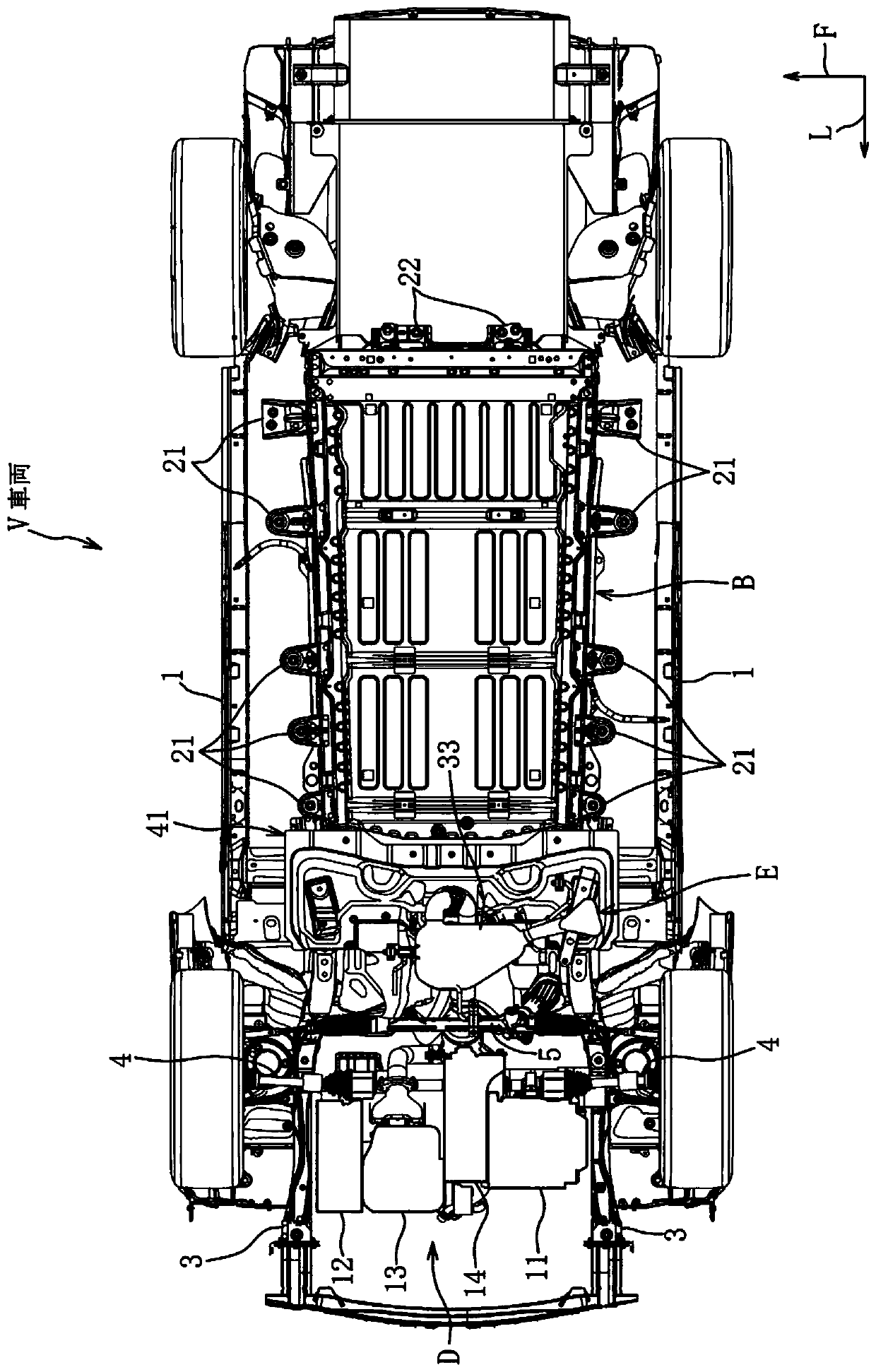
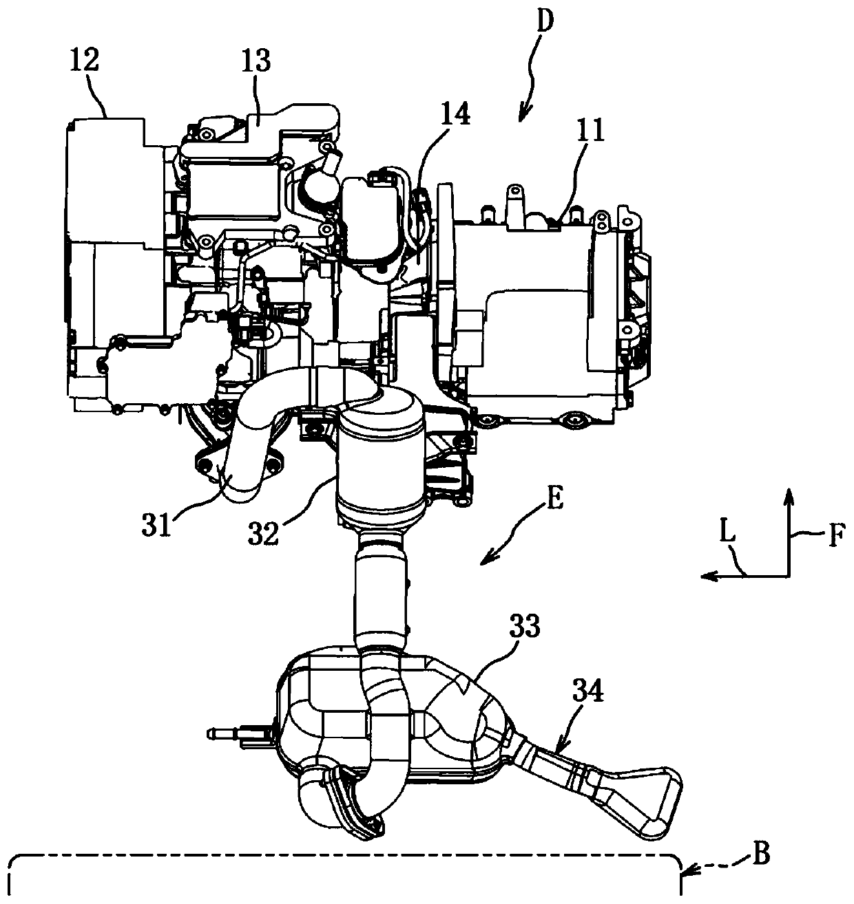
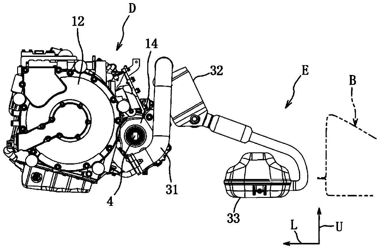
[0045] Such as figure 1 As shown, the electric vehicle V includes a drive unit D for rotationally driving drive wheels, a battery unit B, an exhaust system E, and the like.

[0046] The vehicle V is a range-extended electric vehicle, and it emergency starts the operation of the engine under a preset specific operating condition only when there is a small amount of electric power charged in the battery (for example, SOC is less than 30%), for power generation and charging.

[0047] In addition, a charging plug that can be charged by a normal charger that is a household power supply or a quick charger installed in a parking area or the like may be provided.

[0048] First, the premise structure of the frame members of the vehicle V will be described.

[0049] Such as figure 1 As shown, the vehicle V has: a pair of left and right side beams 1 forming a closed section extendin...


PUM


Abstract

An exhaust structure of a vehicle (V) is provided that can ensure an arrangement space for a mounted component below a floor panel and prevent thermal damage to the mounted component by reducing sizesof an engine and an exhaust silencer. An exhaust structure of a vehicle includes: an engine (13) disposed in an engine bay formed in a front part of a vehicle; a silencer (33) that reduces noise of exhaust gas from the engine and discharges the exhaust gas outside; an exhaust pipe (31) that couples the engine (13) and the silencer (33); and a battery unit (B) disposed behind the engine (13) and below a floor panel (2), the silencer (33) being disposed between the engine (13) and the battery unit (B).

Description

technical field [0001] The present invention relates to an exhaust structure for a vehicle, and more particularly to an exhaust structure for a vehicle including components mounted on the rear side of the engine and under the floor. Background technique [0002] Currently, among electric vehicles, a hybrid vehicle equipped with an engine for power generation is superior to a pure electric vehicle in terms of increased cruising distance and miniaturization of a battery unit. [0003] The vehicle of Patent Document 1 includes an engine disposed at the front of the vehicle body, an exhaust pipe extending rearward from the engine, a box-shaped battery unit fixed to the underside of the floor, and a device-side power transmission device capable of receiving electric power. In the power receiving device, the exhaust pipe is arranged to pass through the lower side of the floor and near the side of the battery unit, and a heat insulating member is provided between the exhaust pipe a...

Claims


Application Information

Patent Timeline
Patent Type & Authority Applications(China)
IPC IPC(8): B60K13/04F01N13/00F01N13/18B60L50/61
CPCB60K13/04F01N13/007F01N13/1805B60L50/61F01N13/009F01N2260/20F01N2340/02F01N2340/04F01N1/00F01N2590/11B60K1/04B60K2001/0438B60Y2200/92B60K5/04Y02T10/62Y02T10/70F01N13/14F01N1/02B60K6/26B60K6/28F01N1/003
Inventor 加茂寿章长谷川裕一伊藤贵广守本翔平
Owner MAZDA MOTOR CORP
Features
  • R&D
  • Intellectual Property
  • Life Sciences
  • Materials
  • Tech Scout
  • Unparalleled Data Quality
  • Higher Quality Content
  • 60% Fewer Hallucinations
Learn More