Supercharge Your Innovation With Domain-Expert AI Agents!

Lighting appliance

A lamp and light source technology, applied in the field of lamp units, can solve problems such as not easy to ensure the space for configuring it, increase in size of lamp units, etc.

Active Publication Date: 2020-07-07
KOITO MFG CO LTD
View PDF6 Cites 0 Cited by
  • Summary
  • Abstract
  • Description
  • Claims
  • Application Information

AI Technical Summary

Problems solved by technology

[0006] On the other hand, in the lamp unit described in the above-mentioned "Patent Document 1", a heat dissipation member for dissipating heat generated by turning on the light source is disposed on the Since the position is closer to the lower side than the light source support member, the size of the lamp unit in the vertical direction increases, and it is difficult to secure a space for its arrangement.

Method used


Image

  • Lighting appliance
  • Lighting appliance
  • Lighting appliance

Examples


Embodiment Construction

[0045] Hereinafter, embodiments of the present invention will be described with reference to the drawings.

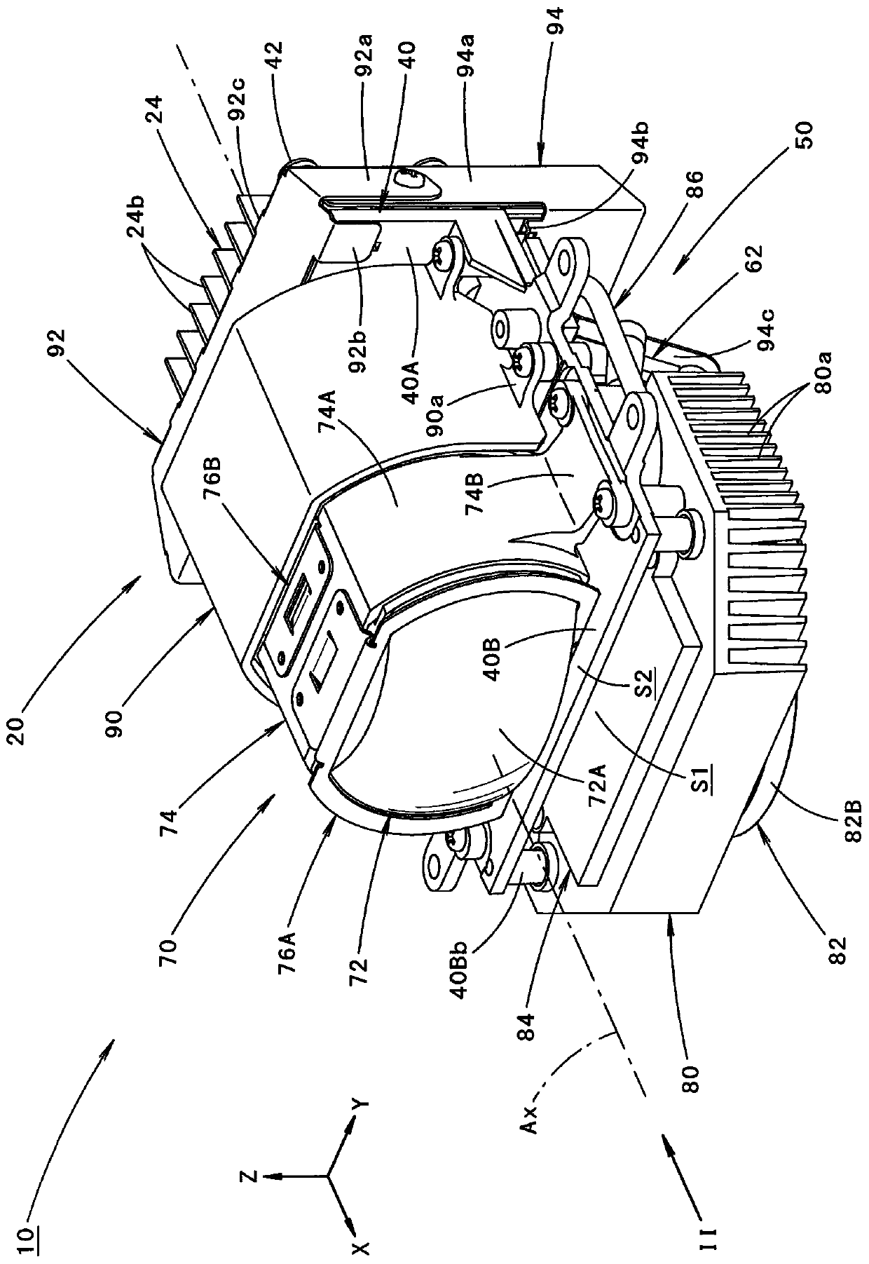
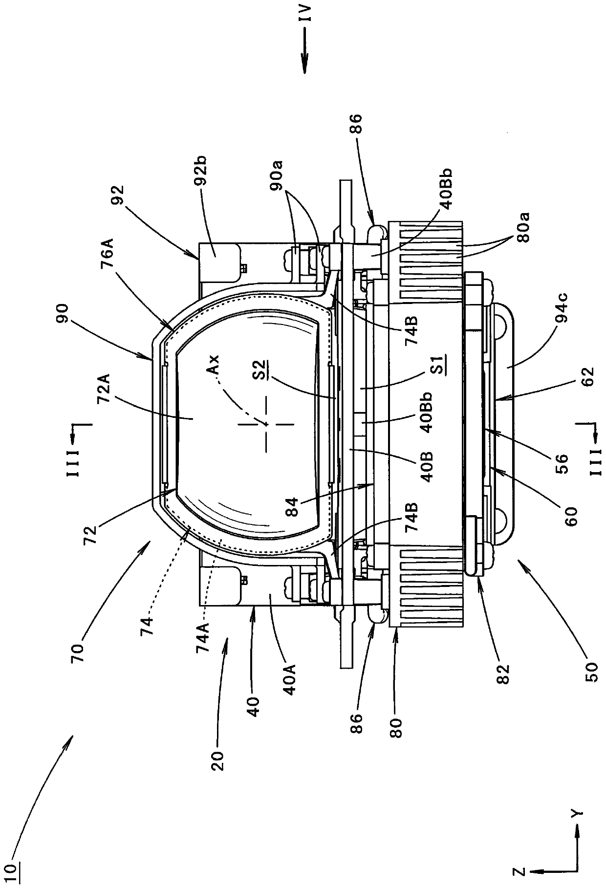
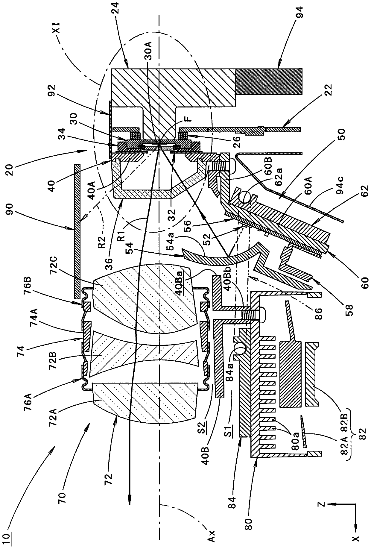
[0046] figure 1 is a perspective view showing a lamp unit 10 according to an embodiment of the present invention, figure 2 yes figure 1 II direction view. in addition, image 3 yes figure 2 Sectional view of line III-III, Figure 4 yes figure 2 View in the direction of IV. in addition, Figure 5 yes Figure 4 The V-direction view, Figure 6 yes Figure 4 VI direction to the view, Figure 7 yes Figure 4 View from direction VII.

[0047] In these figures, the direction indicated by X is "unit front", the direction indicated by Y is "left direction" perpendicular to "unit front" ("right direction" when the unit is viewed from the front), and the direction indicated by Z is " up direction". The same applies to other figures.

[0048] The lamp unit 10 of this embodiment can be assembled into Figure 14 The state of the vehicular lamp 100 shown in the sid...


PUM


Abstract

In a lamp unit having a reflective spatial light modulator, a heat dissipation function can be ensured without increasing the size in the vertical direction even when a light source support member isdisposed below the spatial light modulator. A heat sink (80) for dissipating heat generated by the lighting of the light source is disposed closer to the front side of the cell than a substrate member(60) that supports the light source via a substrate (56) and closer to the lower side than a projection lens (72). A heat transfer plate (84) fixed to the heat sink (80) and a heat transfer plate (62) fixed to the substrate member (60) are connected via a heat pipe (86). Thus, the heat dissipation function can be ensured without increasing the size of the lamp unit (10) in the vertical direction.

Description

technical field [0001] The invention relates to a luminaire unit with a reflective spatial light modulator. Background technique [0002] Conventionally, as a vehicle-mounted lamp unit, a configuration is known in which light from a light source reflected by a spatial light modulator is irradiated forward of the unit through optical components such as a projection lens. [0003] "Patent Document 1" describes that, as the lamp unit as described above, light emitted from a light source is reflected toward a spatial light modulator by a reflector. In this case, in the lamp unit described in "Patent Document 1", the light source supporting member that supports the light source is arranged at a lower side than the spatial light modulator together with the reflector. [0004] Patent Document 1: (Japanese) Unexamined Patent Publication No. 2016-91976 [0005] Like the lamp unit described in the above-mentioned "Patent Document 1", by arranging the light source supporting member a...

Claims


Application Information

Patent Timeline
IPC IPC(8): F21S41/25F21S41/32F21S45/43F21S45/48F21S45/49F21W107/10F21W102/00F21Y115/10
CPCF21S41/25F21S41/32F21S45/43F21S45/48F21S45/49F21W2107/10F21W2102/00F21Y2115/10
Inventor 佐藤隆芳大桥阳介伊藤高志
Owner KOITO MFG CO LTD
Features
  • R&D
  • Intellectual Property
  • Life Sciences
  • Materials
  • Tech Scout
  • Unparalleled Data Quality
  • Higher Quality Content
  • 60% Fewer Hallucinations
Learn More