
smt patch technology and conveying device applied to it

A technology of conveying device and conveyor belt, which is applied in the direction of conveyor, transportation and packaging, etc. It can solve the problems of PCB board inclination, position offset, affecting the quality of patch, etc., and achieve the effect of convenient and fast operation

Active Publication Date: 2021-05-28
深圳市杰瑞佳科技有限公司
View PDF0 Cites 0 Cited by
  • Summary
  • Abstract
  • Description
  • Claims
  • Application Information

AI Technical Summary

Problems solved by technology

[0003] Generally speaking, when performing SMT placement, it mainly goes through the processes of dispensing, parts placement, reflow soldering, AOI optical inspection, maintenance and board splitting. In the existing SMT placement process, after each step of operation, it is necessary to The PCB board is sent to the next station for operation by manual transfer. During the transfer process, the PCB board is prone to inclination, which may easily cause the position of the glue printed on the PCB board and the parts to shift, thereby affecting patch quality

Method used


Image

  • smt patch technology and conveying device applied to it
  • smt patch technology and conveying device applied to it
  • smt patch technology and conveying device applied to it

Examples


Embodiment 1

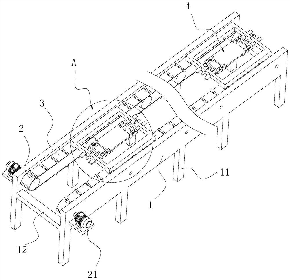
[0038] Embodiment one: a kind of conveying device, see attached figure 1 , including two vertically arranged vertical boards 1 parallel to each other, support legs 11 fixedly connected to the bottoms of both ends of the two vertical boards 1, a number of rotating rollers 2 rotatably connected to one side of the vertical boards 1 close to each other, fixedly connected to the vertical boards 1 is used to drive the motor 21 of one of the rotating rollers 2 to rotate, the conveyor belt 3 sleeved on the rotating roller 2 and the clamping mechanism 4 supported on the two conveyor belts 3; the length directions of the two vertical plates 1 are parallel to each other and the length The direction is set horizontally, the axes of several rotating rollers 2 are perpendicular to the riser 1 and the axes of several rotating rollers 2 are located in the same horizontal plane, and the top surface of the conveyor belt 3 is set horizontally; the PCB board is clamped in the clamping mechanism 4,...

Embodiment 2

[0044] Embodiment two: a kind of SMT patch technology, comprises the following steps:

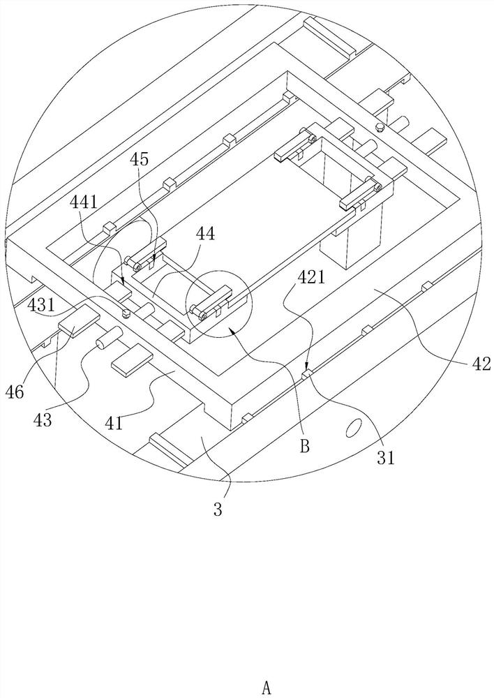
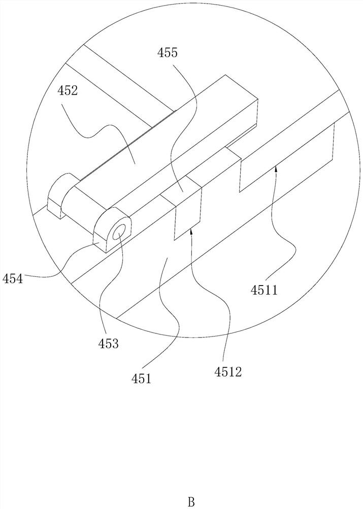
[0045] a. Fixing the PCB board: Insert the two sides of the PCB board into the accommodation grooves 4511 of the four bottom plates 451 respectively, then turn over the pressure plate 452, under the action of the magnetic block 455, the pressure plate 452 fixes the PCB board, and then rotate and connect Rod 43, so that the PCB board is in a horizontal position, insert the positioning plate 46 into the positioning groove 441, and then tighten the fastening bolt 431;

[0046] b. Install the clamping mechanism 4: support the connecting plate 42 on one end of the conveyor belt 3, and insert the positioning protrusion 31 into the corresponding positioning groove 421;

[0047] c. Glue dispensing: The conveyor belt 3 drives the clamping mechanism 4 forward, and the PCB board is transported to the bottom of the glue dispenser. Under the action of the glue dispenser, the glue is printed on the co...


PUM


Abstract

The invention discloses an SMT patching process and a conveying device applied to the process, relates to the technical field of SMT patching, and solves the problem that the glue and components in the existing SMT patching process are prone to positional deviation when the PCB board is transferred The main point of the technical solution is that the conveying device includes two vertical plates, supporting legs, a number of rotating rollers rotatably connected to the sides of the two supporting plates close to each other, a motor fixedly connected to the supporting plates, and a conveyor belt sleeved on the rotating rollers. And the clamping mechanism supported on the two conveyor belts; the patch process includes: a. Fixed PCB board; b. Install the clamping mechanism; c. dispensing; d. check; e. Component placement; f. Reflow soldering; g. AOI test; h. Flip the patch, the conveyor belt transports the clamping mechanism, and passes through the dispenser, the placement machine and the reflow oven in turn, so that the PCB board can be kept flat during the transportation process, so that the glue and parts printed on the PCB board It is not easy to shift the position.

Description

technical field [0001] The invention relates to the technical field of SMT patches, more specifically, it relates to an SMT patch process and a conveying device applied to the process. Background technique [0002] SMT patch refers to the abbreviation of a series of process processes processed on the basis of PCB. PCB is a printed circuit board, and SMT is surface mount technology, which is a popular technology and process in the electronic team leader industry. [0003] Generally speaking, when performing SMT placement, it mainly goes through the processes of dispensing, parts placement, reflow soldering, AOI optical inspection, maintenance and board splitting. In the existing SMT placement process, after each step of operation, it is necessary to The PCB board is sent to the next station for operation by manual transfer. During the transfer process, the PCB board is prone to inclination, which may easily cause the position of the glue printed on the PCB board and the parts...

Claims


Application Information

Patent Timeline
Patent Type & Authority Patents(China)
IPC IPC(8): B65G15/58
CPCB65G15/58
Inventor 曾茂添郑汉武谢宇丰梅靖然岳宗振
Owner 深圳市杰瑞佳科技有限公司
Learn More