
Patsnap Eureka
For R&D, Patsnap Eureka makes reading and utilizing patents & technical documents easy.
Patsnap Eureka AIR
Designed for self-driven R&D workflows. Generate viable solutions, solve complex R&D challenges, empower your innovation with AI.

Patsnap Eureka Materials
Designed for material experts only. Revolutionize your material R&D, from search, analyze, to developing new materials.

TechResearch
Generate reliable direction feasibility study reports for your R&D in just a few steps.

TechSeek
Discover and master advanced knowledge NOW. Basics, ideas, possibilities, all at once.

TechMind
As an expert in R&D Theories, TechMind can generates customized viable solutions instantly.

TechRisk
Analyze your overall solution with one click, know your potential R&D risks in advance.

TechMonitor
Get weekly tech updates, stay abreast of the latest tech innovations and key insights.
Image-based coiled material deviation rectification detection system
A detection system and coil technology, which is applied in the field of coil deviation correction, can solve the problems of unobvious coil edge tracking feature points, unstable deviation correction tracking, and inability to correct deviation, so as to maintain clarity, improve clarity, and improve accuracy Effect
- Summary
- Abstract
- Description
- Claims
- Application Information
AI Technical Summary
Problems solved by technology
Method used
Image

Examples
Embodiment 1
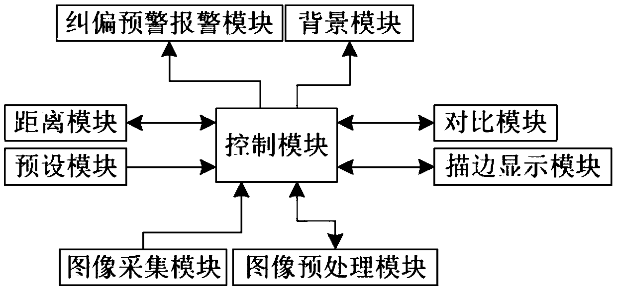
[0034] Image-based coil web guiding detection system, such as figure 1 Shown: including preset module, image acquisition module, background module, image preprocessing module, control module, stroke display module, comparison module, distance module and deviation correction warning and alarm module.
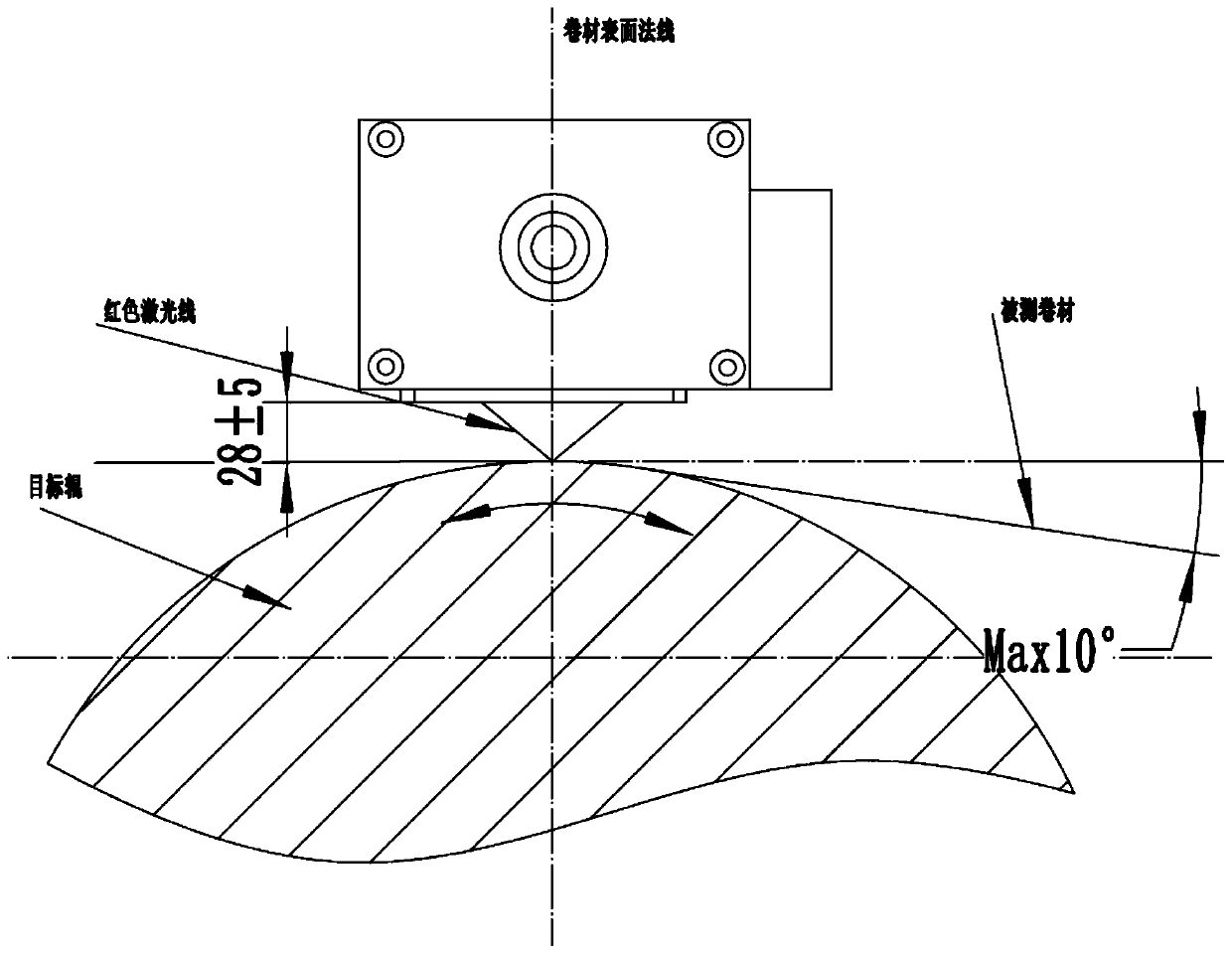
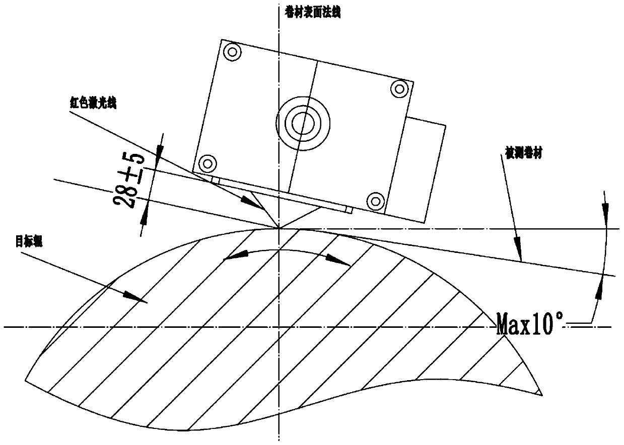
[0035] The image acquisition module includes an exposure unit and multiple laser units. The exposure unit is used to select the exposure mode. The exposure mode includes automatic exposure and manual exposure. The exposure threshold can be set to improve the clarity of the image. For example, the automatic exposure method is generally used. When the contrast of the image is small or the image acquisition target is a coil with serious interference, manual exposure is selected, and the image acquisition module resets through the preset Press the button to restore the default option for the exposure mode (the default option can be manual exposure mode).
[0036] The laser unit is u...
Embodiment 2
[0048] The difference with Embodiment 1 is that, if Figure 4 As shown, it also includes a material module and a substrate module. The material module is used to send the material information of the coil to the control module. The material information includes transparent materials and occlusion materials. The material module obtains material information through image information, because when the coil is transparent Infrared rays cannot be used for deviation correction, so the material can not be blocked when infrared rays are detected, and the control module controls the substrate module to substrate the image information of the coiled material according to the material information.
[0049] Such as Figure 5 As shown, the substrate module includes an anti-color bottom plate and a power mechanism. The power mechanism can use an existing servo motor. The control module controls the 180° of each rotation of the servo motor to turn over the anti-color bottom plate. The control ...
PUM
 Abstract
Description
Claims
Application Information
 - R&D Engineer
- R&D Manager
- IP Professional
- Industry Leading Data Capabilities
- Powerful AI technology
- Patent DNA Extraction
Browse by: Latest US Patents, China's latest patents, Technical Efficacy Thesaurus, Application Domain, Technology Topic, Popular Technical Reports.
© 2024 PatSnap. All rights reserved.Legal|Privacy policy|Modern Slavery Act Transparency Statement|Sitemap|About US| Contact US: help@patsnap.com