Three-cavity spring braking gas chamber

A technology of spring brake air chamber and spring cavity, which is applied in the direction of brake actuator, gear transmission mechanism, mechanical equipment, etc., can solve the problems of inconvenient operation of the brake air chamber, inability to apply the parking brake normally, etc.

Pending Publication Date: 2020-02-11
重庆凯瑞传动技术有限公司 +1
View PDF0 Cites 0 Cited by
  • Summary
  • Abstract
  • Description
  • Claims
  • Application Information

AI Technical Summary

Problems solved by technology

[0004] The purpose of the present invention is to provide a three-chamber spring brake air chamber to solve the problem that the existing brake air chamber is inconvenient to operate forcibly released, and the parking brake cannot be normally applied after the forced release is implemented.

Method used


Image

  • Three-cavity spring braking gas chamber
  • Three-cavity spring braking gas chamber
  • Three-cavity spring braking gas chamber

Examples


Embodiment

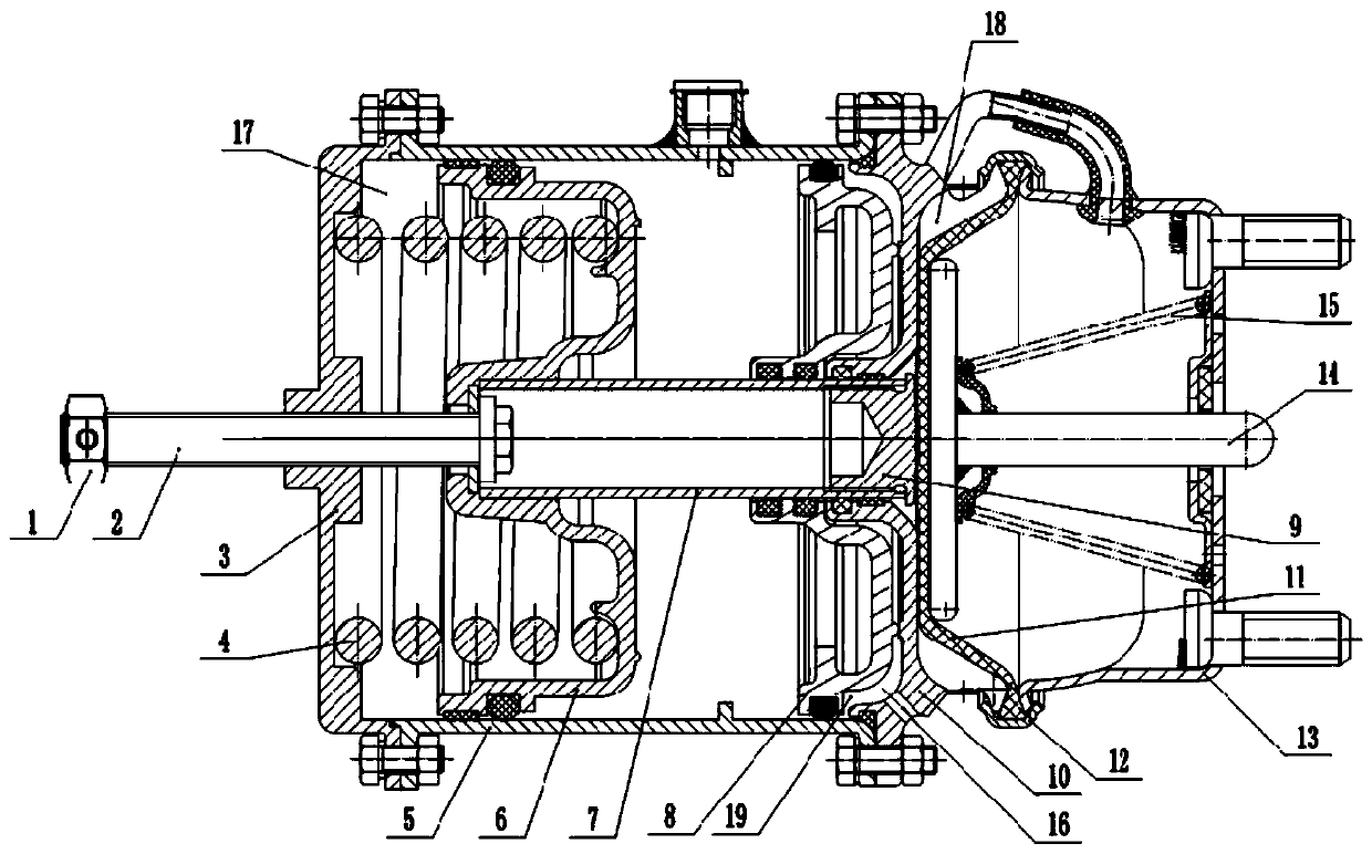
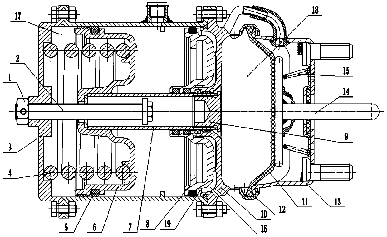
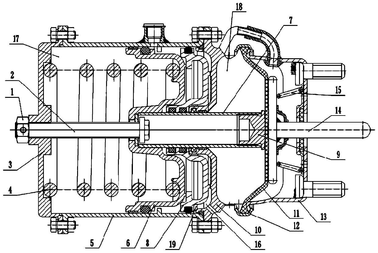
[0024] A three-chamber spring brake chamber, as attached figure 1 As shown, it mainly consists of cylinder body 5, cover plate 3, connecting seat 10, fixed seat 13, screw rod 2, hollow cylinder 7, parking piston 6, parking brake spring 4, relief piston 8, diaphragm 11, lock ring 12, Push rod 14, back-moving spring 15 constitute.

[0025] The left side of the cylinder body 5 is connected with the cover plate 3 by bolts, and the right side of the cylinder body 5 is connected with the connecting seat 10 by bolts. The left part of the cylinder body 5 is slidably connected with a parking piston 6, and a spring chamber 17 is formed between the cover plate 3 and the parking piston 6, and a parking brake spring 4 is installed in the spring chamber 17.

[0026] The right part of the cylinder block 5 is slidably connected with a relief piston 8, and a parking brake chamber is formed between the relief piston 8 and the parking piston 6, and the parking brake chamber is connected with an...


PUM


Abstract

The invention relates to the field of vehicle braking systems, and discloses a three-cavity spring braking gas chamber. The three-cavity spring braking gas chamber comprises a cylinder body, a connecting base and a fixing base. A spring cavity is formed in the cylinder body. A membrane cavity is formed between the connecting base and the fixing base. A relief piston is further connected with the interior of the cylinder body in a sliding mode, and a remote control forced relief cavity is formed between the relief piston and the connecting base. A communicating opening which is used for communicating with the external gas is formed in the connecting base. By the adoption of the scheme, the forced relief can be relatively conveniently achieved, and the parking braking operation can also be normally applied after the forced relief is accomplished.

Description

technical field [0001] The invention belongs to the field of vehicle brake systems. Background technique [0002] The spring brake air chamber is widely used in the car brake system and is installed on the drive axle of the car to provide braking force for the car. It is mainly composed of two parts: the diaphragm cavity is used for service braking; the spring cavity is used for auxiliary braking and parking braking, and a mechanical relief mechanism is provided to realize forced relief. [0003] With this kind of brake chamber, when the brake fails to be released normally, the driver and passengers need to get off the car, manually screw the screw with a tool, unscrew the screw and compress the parking brake spring to achieve forced relief, which is inconvenient to operate. And the parking brake can no longer be applied normally after the forced release. Contents of the invention [0004] The object of the present invention is to provide a three-chamber spring brake air...

Claims


Application Information

Patent Timeline
Patent Type & Authority Applications(China)
IPC IPC(8): F16D65/14F16D121/08F16D125/04F16D125/08F16D125/16
CPCF16D65/14F16D2121/08F16D2125/04F16D2125/08F16D2125/16
Inventor 李科先俊臣钟徐波郭光林卿鹏
Owner 重庆凯瑞传动技术有限公司
Why Eureka
Try Eureka