Treatment Process for Polluted Oil Sludge

Inactive Publication Date: 2019-10-03
REN HANG
View PDF0 Cites 5 Cited by
  • Summary
  • Abstract
  • Description
  • Claims
  • Application Information

AI Technical Summary

Benefits of technology

The patent describes a process for turning polluted oil sludge into safe and reusable materials. It involves crushing and sieving the sludge, mixing it with water and a treatment agent, and then separating the solid and liquid phases. The solid phase is then treated with a recoverable treatment agent composition, resulting in a high removal rate of oil content. The treated sludge can be reused for farming purposes. The advantages of this process include its simplicity, wide application range, and ability to recycle and reuse wastewater.

Problems solved by technology

Such oil sludge is characterized by high oil content, high viscosity, fine particle size, and difficulty to dehydrate, among others.
The composition of oil sludge is extremely complex.
If these substances are not properly treated, direct discharge of the oil sludge will seriously pollute the surrounding soil, water bodies, vegetation, and the atmosphere, thereby deteriorating the ecological environment as a whole.
Therefore, it would be wasteful to directly discharge the oil sludge.
Currently, treatment and recycling of oil sludge is still considered a major problem for the oil industry.
Although solvent extraction is thorough and effective, it currently has the disadvantage of lacking a highly efficient, pollution-free, and low safety risk extractant.
Second, the problem of operation loss of the extractant has not yet been addressed in a satisfactory manner, resulting in high cost such that it cannot be broadly promoted and used.
This process requires high equipment and operating costs, high consumption of energy from combustion and high consumption of aiding agent.
Moreover, the method can easily produce secondary pollutants such as flue gas, thereby increasing processing costs.
Chemical cleaning agents have a detrimental effect on the environment and are highly specific and single purposed, and may have lower than expected effect or become even completely ineffective when the treatment object changes.
Here, operating costs are low, but microbial cultures are difficult to develop and have a long operating cycle.
Moreover, sewage oil cannot be recovered, resulting in waste of potential resources, and may easily result in secondary pollution.
Once a leak occurs, the surrounding soil and even underground water will likely be polluted.
The refinery oil sludge disposal system and method disclosed in Chinese publication CN 107500501 A uses high temperature pyrolysis above 400° C. Although the degree of reduction is over 96%, its energy consumption is high, and smoke and other harmful substances are generated during the treatment process, causing secondary threat to the environment.
Although its treatment effect is good, the preparation of its treatment agents is complex.
Also, the types of sludge applicable is narrow in scope, and the processing cycle is more than half a month.
While its sludge treatment effect is good, it requires outdoor exposure and fermentation for more than 20 days.
Moreover, the required operating floor space is large, and the treatment period is long.
Finally, the oil sludge treatment method described in Chinese publication CN 107253810 A can only reduce oil content of the oil sludge to less than 2% after several treatments rounds, thus failing to meet the standards for agricultural soil use.

Method used


Image

  • Treatment Process for Polluted Oil Sludge
  • Treatment Process for Polluted Oil Sludge

Examples


example 1

[0059]Tank bottom sludge of an oil depot is treated in this example. The sludge selected is a viscous black substance with certain fluidity. Crude oil and water envelop the sediment. The material system is uniform. The oil content of the sludge is 58.67%, and the water content is 20.13%. The rest of the content is sediment.

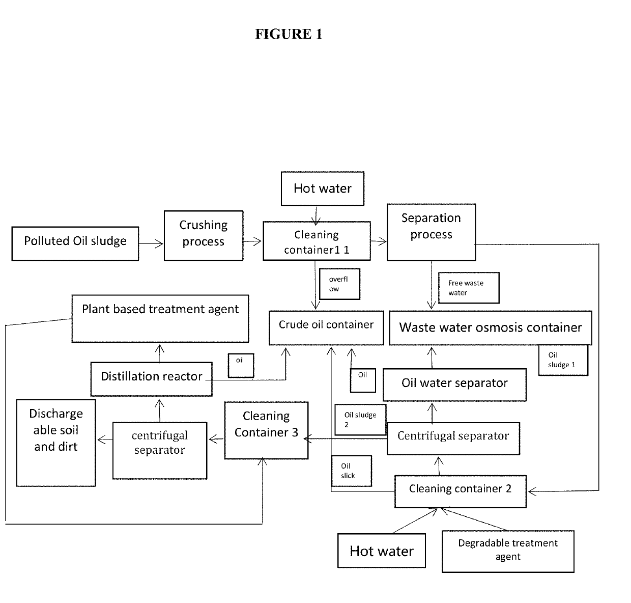
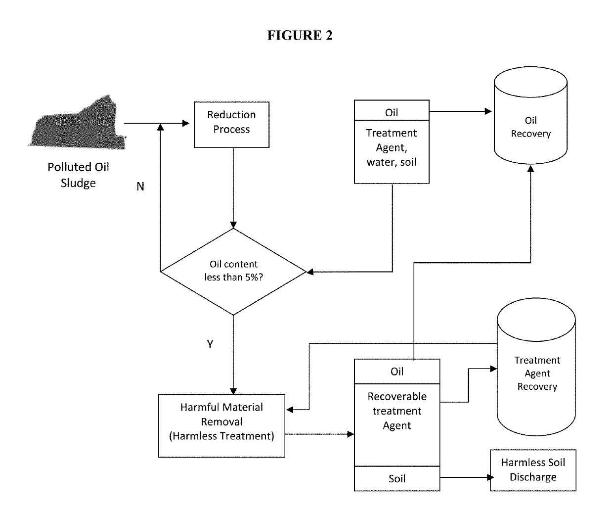
[0060]A treatment method per the present invention is used, which comprise the steps as shown in FIG. 2 (Basic Flow Chart), and use basic assembly of systems and equipment as shown in FIG. 1. More specifically, the treatment is discussed in more detail below.

[0061](1) Pick out the larger stones, plastic trash, tree branches, and other waste materials from the oil sludge sample. Using a screw feeder, the sludge is pushed into a mixing and cleaning tank filled with a certain amount of water in advance at a certain propulsion speed. The ratio of material to liquid is 1:3, stirred at 600 r / min and the mixture is heated to 70° C. After 60 minutes, stirring is stopped a...

example 2

[0067]Oil field oil sludge is used in this example. The sludge selected is a viscous black substance with little mobility. The sludge contains 67.2% of oil, 10% of water, and the rest is silt.

[0068]A treatment method per the present invention is used, which comprise the steps as shown in FIG. 2 (Basic Flow Chart), and use basic assembly of systems and equipment as shown in FIG. 1. More specifically, the treatment is discussed in more detail below.

[0069](1) Pick out the larger stones, plastic trash, tree branches, and other waste materials from the oil sludge sample. Using a screw feeder, the sludge is pushed into a mixing and cleaning tank filled with a certain amount of water in advance at a certain propulsion speed. The ratio of material to liquid is 1:1, stirred at 600 r / min and the mixture is heated to 70° C. After 60 minutes, the stirring is stopped and the materials are allowed to stand for 15 minutes. After stratification, the oil is surfaced as slick and discharged by overfl...

example 3

[0075]Oil sludge of an oil refinery is used in this example. The sludge selected is a viscous black substance with no mobility, fine and uniform particle size, with no impurities. The sludge contains 40.2% of oil, 50% of water, and the rest is silt.

[0076]A treatment method per the present invention is used, which comprise the steps as shown in FIG. 2 (Basic Flow Chart), and use basic assembly of systems and equipment as shown in FIG. 1. More specifically, the treatment is discussed in more detail below.

[0077](1) Using a screw feeder, the sludge is pushed into a mixing and cleaning tank filled with a certain amount of water in advance at a certain propulsion speed. The ratio of material to liquid is 1:1.5, stirred at 300 r / min and the mixture is heated to 70° C. After 60 minutes, the stirring is stopped and the materials are allowed to stand for 60 minutes. After the stratification, the oil is surfaced as slick and discharged by overflow to the oil recovery tank, and the remainder ma...


PUM

PropertyMeasurementUnit
Temperatureaaaaaaaaaa
Lengthaaaaaaaaaa

Abstract

Treatment systems, agents and processes are described for processing polluted oil sludge into environmentally harmless and reusable resources. The oil sludge is first crushed, mixed with water, stirred, and stratified, then the overflow layer with the oil slick is transferred into oil recovery tank; the remaining mixture of solid and liquid is then subjected to centrifugal solid-liquid separation, the resulting free water is collected for reuse through osmosis, and the remaining solid phase material goes through a secondary oil content reduction treatment, adding water, degradable treatment agent, stirring, and after the system was standing stratified, the upper layer with the oil slick is overflowed and transferred to oil recovery tank; for the mixture from the centrifugation separation and reduction treatment processes, the resulting liquid phase is subjected to oil water separation, the oil phase is transferred into the oil recovery tank, the water phase enters into the wastewater recycling tank for recycle and reuse, the remaining solid phase is treated to become environmentally harmless materials; undergo centrifugal separation again, and the liquid phase is distilled to recover the plant based treatment agent, the remaining oil is transferred to the oil recovery tank, and the excess sludge is dried.

Description

FIELD OF THE INVENTION[0001]This application relates to the field of petroleum environmental protection, in particular to a harmless oil sludge treatment process to separate and recover useful resources such as crude oil from within the sludge, and render the resulting sludge harmless.DISCUSSION AND COMPARISON WITH RELEVANT PRIOR ART[0002]Oil saturated sludge in oil fields is an oil-containing hazardous solid waste generated during oil field development, oil product storage and transportation, and refining and development process. Such oil sludge is characterized by high oil content, high viscosity, fine particle size, and difficulty to dehydrate, among others. The composition of oil sludge is extremely complex. It generally contains large amounts of aged crude oils, waxes, asphaltenes, colloids and suspended solids, bacteria, salts, acidic gases, and small amounts of heavy metal salts such as copper, zinc, chromium, and mercury. At the same time, it can contain odoriferous toxic su...

Claims


Application Information

Patent Timeline
IPC IPC(8): C10G1/04C10G17/10C10G21/20C10G21/28B01D45/12B01D3/14
CPCC10G21/28B01D45/12C10G1/04C10G2300/1003C10G17/10B01D3/14C10G21/20C02F11/00C02F11/12C02F11/127C02F2303/26C02F2305/04C02F2303/06C02F11/148C02F2103/365B01D17/0217B01D17/047Y02W10/40
Inventor REN, HANG
Owner REN HANG
Why Eureka
Try Eureka