Medium-wave infrared long-focus lens

A focal length and lens technology, applied in the optical field, can solve the problems of small focal power, long focal length, and inappropriateness, and achieve the effect of light weight, small size, and reduced overall length

Active Publication Date: 2020-02-11
SHANGHAI INST OF TECHNICAL PHYSICS - CHINESE ACAD OF SCI
View PDF1 Cites 0 Cited by
  • Summary
  • Abstract
  • Description
  • Claims
  • Application Information

AI Technical Summary

Problems solved by technology

[0006] As far as the optical system shown in Document 1 is concerned, although a catadioptric system is used to provide a large-aperture-ratio, mid-wave infrared telescope optical system, the focal length of the mirror group composed of primary and secondary mirrors is too long, and the focal power If it is too small, the size of the entire system is too long, which is not suitable for the dynamic target tracking and observation requirements required in recent years

Method used


Image

  • Medium-wave infrared long-focus lens
  • Medium-wave infrared long-focus lens
  • Medium-wave infrared long-focus lens

Examples


Embodiment 1

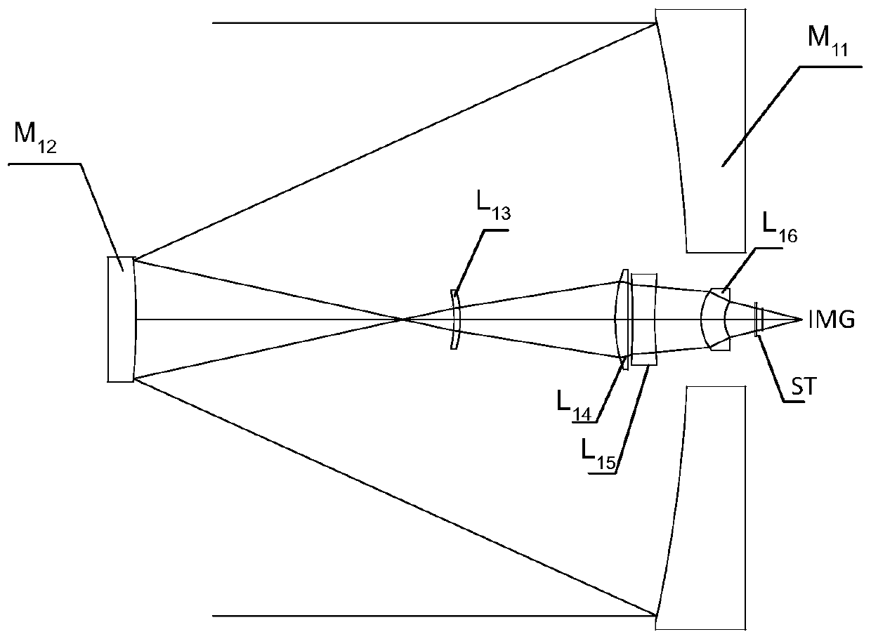
[0054] figure 1It is a sectional view along the optical axis showing the structure of the telephoto lens of Example 1. The long focal length lens is composed of: a reflection mirror group with positive refractive power and a transmission mirror group with positive refractive power. The reflector group is constituted as, the main reflector M 11 , the secondary reflector M 12 ; The lens group is composed of: positive lens L 13 , positive lens L 14 , negative lens L 15 and positive lens L 16 , followed by a cold stop ST and an image plane IMG.

[0055] Various numerical data about the mid-wave infrared telephoto lens of Example 1 are shown below.

[0056] (basic data of the optical system)

[0057] name Face number type radius of curvature thickness Material S0 object side INF INF primary mirror M1 Aspherical -721.32 -290.37 secondary mirror M2 sphere -297.70 167.12 lens 1 S3 sphere -68.43 3.20 silicon ...

Embodiment 2

[0063] Figure 4 It is a sectional view along the optical axis showing the structure of the telephoto lens of Example 2. The long focal length lens is composed of: a reflection mirror group with positive refractive power and a transmission mirror group with positive refractive power. The reflector group is constituted as, the main reflector M 21 , the secondary reflector M 22 ; The lens group consists of: negative lens L 23 , positive lens L 24 , negative lens L 25 and positive lens L 26 , followed by a cold stop ST and an image plane IMG.

[0064] Various numerical data about the mid-wave infrared telephoto lens of Example 2 are shown below.

[0065] (basic data of the optical system)

[0066] name Face number type radius of curvature thickness Material S0 object side INF 0.000 primary mirror M1 Aspherical -632.94 -225.00 secondary mirror M2 sphere -586.07 173.72 lens 1 S3 Aspherical 55.99 8.00 germa...

Embodiment 3

[0070] Figure 7 It is a sectional view along the optical axis showing the structure of the telephoto lens of Example 3. The long focal length lens is composed of: a reflection mirror group with positive refractive power and a transmission mirror group with positive refractive power. The reflector group is constituted as, the main reflector M 31 , the secondary reflector M 32 ; The transmission lens group is composed of: negative lens L 33 , positive lens L 34 and positive lens L 35 , followed by a cold stop ST and an image plane IMG.

[0071] Various numerical data about the mid-wave infrared telephoto lens of Example 3 are shown below.

[0072] (basic data of the optical system)

[0073] name Face number type radius of curvature thickness Material S0 object side INF 0.000 primary mirror M1 Aspherical -492.01 -173.63 secondary mirror M2 Aspherical -422.29 61.73 S3 INF 61.73 lens 1 S4 Aspheric...


PUM


Abstract

The invention discloses a medium-wave infrared long-focus lens. The medium-wave infrared long-focus lens comprises the following optical elements arranged in order from an object side: a reflector group with positive focal power and a lens group with positive focal power, and is characterized in that the medium-wave infrared long-focus lens meets the following conditional expressions: 1.08>=|F1 / F|>=0.62, wherein F represents the full-system focal length of the medium-wave infrared long-focus lens, and F1 represents the focal length of the reflector group. The medium-wave infrared long-focus lens has the beneficial effects that the medium-wave infrared long-focus lens with a large aperture, a large aperture diaphragm, the high resolution and an excellent imaging performance can be provided.

Description

technical field [0001] The invention belongs to the field of optical technology, in particular to a mid-wave infrared telephoto lens. Background technique [0002] In recent years, the application breadth and depth of infrared imaging technology have made considerable progress. Due to its high sensitivity and its price, the medium-wave cooling detector has obvious advantages over the same type of long-wave infrared detector. It has broad application prospects in military and related civilian fields such as detection and intelligence reconnaissance. Especially for the early detection of ultra-long-distance targets, the scanning and discovery of low-radiation stealth targets, and the tracking and detection of ultra-high-speed targets, higher sensitivity and higher energy collection are required. Compared with the transmissive system, which is limited by the size of the infrared light-transmitting material, the reflective system has the advantages of no chromatic aberration, l...

Claims


Application Information

Patent Timeline
Patent Type & Authority Applications(China)
IPC IPC(8): G02B17/08
CPCG02B17/0812
Inventor 虞翔孙浩崔文楠张涛
Owner SHANGHAI INST OF TECHNICAL PHYSICS - CHINESE ACAD OF SCI
Why Eureka
Try Eureka