A two-degree-of-freedom portable root washing machine

A portable root washing machine technology, applied in cleaning methods and appliances, chemical instruments and methods, cleaning methods using liquids, etc., can solve the problems of high labor intensity, reduce the progress of research, and low work efficiency, and achieve simple use , Improve cleaning speed and efficiency, and facilitate work efficiency

Active Publication Date: 2021-10-19
SOUTH CHINA AGRI UNIV
View PDF6 Cites 0 Cited by
  • Summary
  • Abstract
  • Description
  • Claims
  • Application Information

AI Technical Summary

Problems solved by technology

[0004] The purpose of the present invention is to solve the problem that when cleaning the root silt of plants in the prior art, it is all done manually by researchers. The whole process is time-consuming, labor-intensive, and has low work efficiency, which greatly reduces the progress of research. To bring great inconvenience to researchers, provide a two-degree-of-freedom portable root washing machine with automatic cleaning, easy use and high work efficiency

Method used


Image

  • A two-degree-of-freedom portable root washing machine
  • A two-degree-of-freedom portable root washing machine
  • A two-degree-of-freedom portable root washing machine

Examples


Embodiment

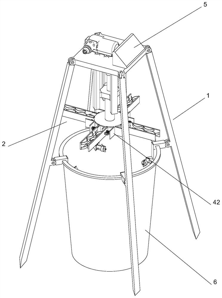
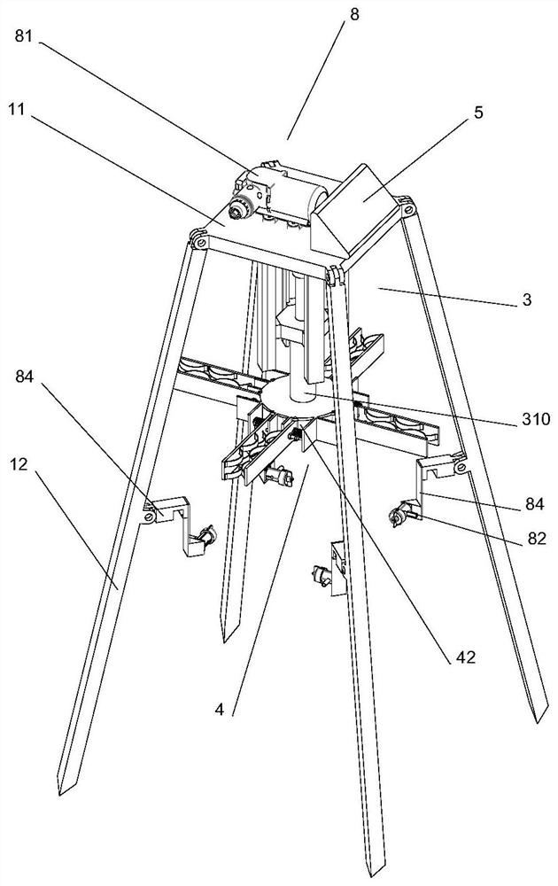
[0027] refer to Figure 1 to Figure 4 , the present embodiment relates to a root washing machine, comprising a support 1, a clamping device 2, a lifting device 3, a swing device 4 and a controller 5 arranged on the support 1, the lifting device 3 is arranged on the support 1, and the lifting device The power output end of the swing device 3 is connected to the swing device 4 to drive the swing device 4 to slide in the vertical direction, and the power output end of the swing device 4 is connected to the clamping device 2 to drive the clamping device 2 to swing; The clamping device 2 clamps the stalk of the plant, and the root of the plant is downward; a water reservoir 6 is provided under the clamping device 2, and the controller 5 controls the lifting device 3 to drive the swing device 4 and the clamping device 2 slide in the vertical direction to immerse the roots of the plants into or leave the water, and at the same time the controller 5 controls the swing device 4 to driv...

Embodiment 2

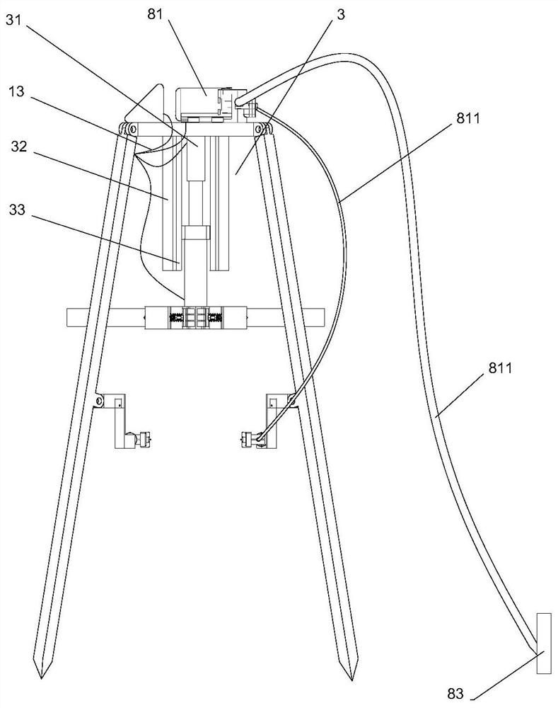
[0041] This embodiment is based on Embodiment 1, and as an improvement to the lifting device 3, the lifting device 3 includes a telescopic motor 31, a guide rail 32 and a slider 33, and the guide rail 32 is vertically fixedly installed on the support 1, The slide block 33 is slidably mounted on the guide rail 32, and the swing device 4 is fixedly mounted on the slide block 33; the telescopic motor 31 is fixedly mounted on the support 1, and the piston rod of the telescopic motor 31 is vertically arranged and connected to the The swing device 4 is fixedly connected, and the telescopic motor 31 is electrically connected with the controller 5 . Under the guidance of the guide rail 32 , the slider 33 can only move vertically along the length direction of the guide rail 32 . When the controller 5 controls the piston rod of the telescopic motor 31 to extend, the telescopic motor 31 drives the swing device 4 and the clamping device 2 to move downward.


PUM


Abstract

The invention discloses a two-degree-of-freedom portable root washing machine, which includes a bracket, a clamping device, a lifting device, a swinging device and a controller. The lifting device drives the swinging device to slide in the vertical direction, and the swinging device drives the clamping device to swing; The clamping device clamps the stem of the plant, and the root of the plant is downward; there is a water reservoir under the clamping device, and the controller controls the lifting device to drive the clamping device to slide to immerse or leave the root of the plant in the water, and at the same time The controller controls the oscillating device to drive the clamping device to oscillate to throw the roots of the plants into or out of the water, and the silt at the roots of the plants repeatedly impacts into the water and falls into the water storage. The root of the plant of the present invention is thrown into or out of the water, so that the sediment on the root of the plant is repeatedly impacted and cleaned and then dropped into the water in the water storage, thereby realizing the function of automatically cleaning the sediment on the root of the plant without The root of the plant is manually shaken for cleaning, which is simple, convenient and efficient.

Description

technical field [0001] The invention belongs to the field of agricultural equipment research, in particular to a two-degree-of-freedom portable root washing machine. Background technique [0002] As early as the 19th century, many experts and scholars in the field of agriculture began to study the morphological characteristics, growth conditions, structural characteristics, and absorption of nutrients of plant roots and other related aspects. Therefore, before performing experimental research on plant roots, it is necessary to clean the plant roots for better observation and experimental analysis. [0003] At present, when cleaning the roots of plants, they are all cleaned manually by researchers. The whole process is time-consuming, labor-intensive, and low in work efficiency, which greatly reduces the progress of research and brings great benefits to researchers. the inconvenience. Contents of the invention [0004] The purpose of the present invention is to solve the ...

Claims


Application Information

Patent Timeline
Patent Type & Authority Patents(China)
IPC IPC(8): B08B3/10
CPCB08B3/10
Inventor 贾瑞昌王志敏梁钰澎
Owner SOUTH CHINA AGRI UNIV
Why Eureka
Try Eureka